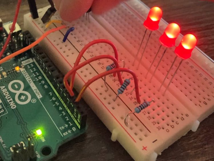
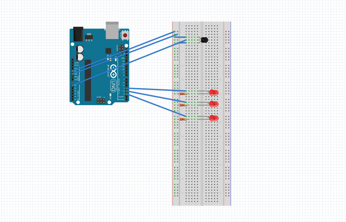
This project was very interesting, showing the basics of how outside physical factors, with a little bit more advanced coding, can effect electronics. The board itself was pretty simple to set up. A parallel circuit for all the LEDs are set up to the Arduino pins 2, 3, and 4. Each of those had a 220ohm resistor attached and grounded. From the A0 (Analog Input 0) slot, we connected a wire to the new factor for the project, the temperature sensor. The three pronged part is interesting to plug in. The top is the power, middle is the analog input, and the bottom is the ground. With the circuit being build we moved over to Arduino IDE to look into the coding. This had many new factors brought in such as constants, which were used to keep the number of the analog sensor pin, as well as the temperature that will affect the sensor. The temperature sensor is then read in the loop, where we made an analogread() function, so the voltage from the pin could be read onto IDE, then being displayed with the displayprint function. The temperature is then read physically through the data. With a few if and elseif statements and a few mathematical formulas, we write out the behavior for the leds to light up as the temperature is read in the sensor.


_ztBMuBhMHo.jpg?auto=compress%2Cformat&w=48&h=48&fit=fill&bg=ffffff)


Comments
Please log in or sign up to comment.