In today's increasingly computational world, it is important to educate young learners about digital logic and its applications. However, there are two main challenges when it comes to teaching a young audience about logic using existing solutions -- (1) Digital logic is an abstract concept, and there needs to be a way to better represent it in an east-to-understand fashion; (2) Existing education solutions are heavily mathematical and rely mostly on computer software. There lacks a hands on component, which has been proven to be beneficial in learning. This project aims to create a building block to a solution to this problem by creating an arcade style logic gate sandbox that employs the hands-on approach as well as a multimodel learning experience (with both visual and auditory feedback, provided by an led strip and a speaker respectively).
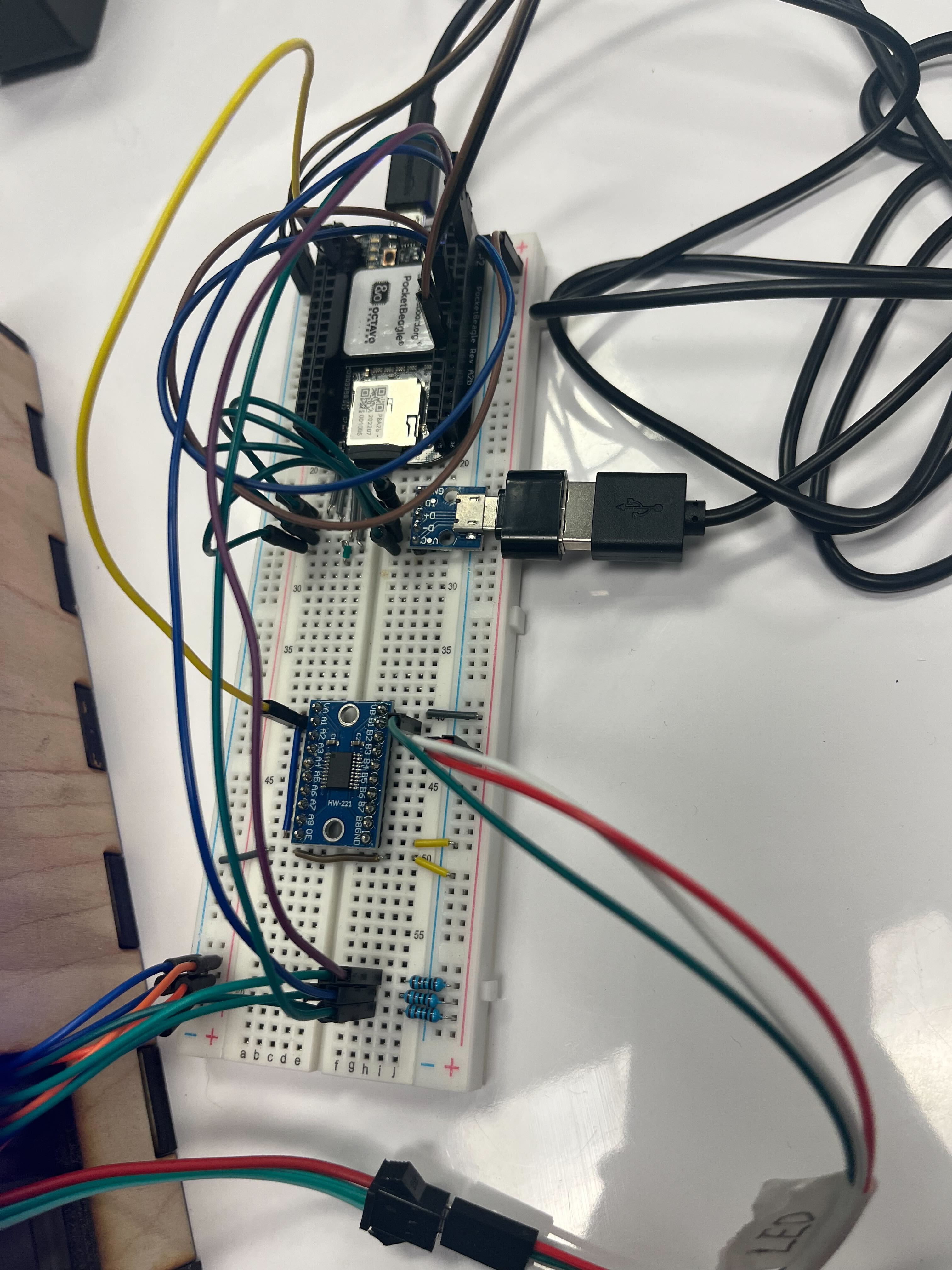
The interactive portion of the sandbox contains three arcade buttons, and an led strip. The buttons are secured with the quick-turn knobs while the leds are secured with tape. The LED strips had to modified to fit the shape of the logic table and the size of the box. This was done by soldering individual strips together and organizing wires with the help of some wire connectors.
The enclosure of the electronics was based on a file generated using makeabox.io The cut outs for the logic table as well as the slots for the led strip were added using Adobe Illustrator. We also added a cutout on the right side of the box to route the wires out. A screenshot of the enclosure design can be found below, and you can also find the pdf file linked in this document.
The enclosure is made of a sheet of 1/4" thick plywood and fabricated using an Epilog laser cutter. it is important to make sure the lens of the laser cutter is clean and that the speed is set properly. Otherwise, the quality of the cut will be low and the piece may snap easily, as shown below. However, this mistake was corrected in the final prototype shown in Figure 1.
Finally, with the completed software drivers and properly prepped hardware, we integrated the system. The demo goes:
1. When the software is launched, it will run through a start-up routine to check the ocnnectivity of the string led -- each light will light up to a soft white color sequentially.
2. The user will be prompted to press and hold the red button. Upon press, the first row of the logic table should turn on in red and stay on until other buttons are pressed.
3. The user will be pressing the blue and green buttons, which correspond to the x input and the y input respectively. When the blue button is pressed, setting the x input to be 1, the second row of the logic table will light up, demonstrating the x, y, and z values in an AND gate with x = 1 and y = 0. Similarly, when the green button is pressed, setting the y input to be 1, the third row of the logic table will light up, demonstrating the x, y, and z values in an AND gate with x = 0, y = 1.
4. Finally, if the user presses both the blue and the green buttons simultaneously, setting both the x input and the y input to be 1, the last row of the logic table will light up in green.
5. At the end of the demo, the sandbox will run through a finish-up routine, lighting each light up to a soft purple color.
A video demo can be found below


_3u05Tpwasz.png?auto=compress%2Cformat&w=40&h=40&fit=fillmax&bg=fff&dpr=2)
Comments
Please log in or sign up to comment.