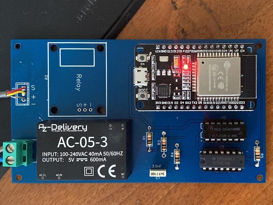
The purpose of this project, was to develope a BLE relay device for Home Assistant that, for the most of time, was in a very low energy and emission state and only for few seconds per minute was in awake state.
At the same time I didn’t need that my ON/Off remote commands was executed instantaneously but, for my needs, was enough that every ON/Off command was really executed within a time interval of one minute.
In other words, for my needs (i.e. to start and stop an aged fan coil unit), it's really unimportant that there is a time delay of at most one minute between the press of the button on the Home Assistant’s dashboard and the effective change of the relay state (that turn off or turn on the fan coil unit).
The project is entirely based on two ESP32 boards, the first acting as a remote BLE server and the second, integrated on the HA platform, acting as BLE client.
At the same time Home Assistant is hosted on a Raspberry Pi 4 Model B.
The remote ESP32 (BLE server) control the relay state by means of an output pin (GPIO 25).
Anyway, since the voltage level of the output pin is high only when the the ESP32 remote server is awake and back to zero volts when the ESP 32 goes in deep sleep state, is needed a way to convert the momentary pulse on GPIO 25 output pin in a permanent signal.
In other words, i.e., if I want that the fan coil is switched on, I need to push the button on the Home assistant dashboard so that a momentary pulse is sent to the output pin during the brief interval in wich the remote ESP32 in awake state and then this pulse is converted in a permanent signal that mantain the relay state ON and the thus the fan coil.
Obviously, to switch the fan coil off, a second pulse will be needed and within the same time interval (about 60 secs) the fan coil will be off.
To do all this, two things are essentially required:
- A BLE connection between the two ESP 32 boards: the first (an HA integration), acting as BLE client and the second, the remote BLE server (directly connected to relay as we said).
- A "momentary switch to toggle switch" logic converter.
Here is the piece of.yaml file in wich you can do all that:
In wich you must specify
1) MAC Address of the Remote ESP32 server server board (i.e.11:22:33:44:55:66)
2) Exposed service UUID and Characteristic UUID (see this to create your own UUID Online UUID Generator Tool)
3) BLE client automation to perform when the client connects to BLE server so that on the HA dashboard you can monitor when the remote ESP32 board is awake and when it sleep.
The second problem, is solved using the well known logic circuit that use a D-Type flip-flop to convert a momentary switch in a toggle switch (see this fora clear explanation of how it works: Convert a Momentary Switch to a Toggle Switch ).
Finally, on the remote ESP32 server, there is a feedback sensor (GPIO 34) to verify if the relay state is really ON or OFF.
Even this data have been sent over a BLE communication between server and client:
As I said, for this project I need essentially two ESP32 boards: one BLE server and one BLE client.
Let me start with the BLE client.
It is a ESP32 board that is used as a BLE tracker and is directly connected to the Home Assistant platform that is hosted on the Raspberry PI 4 model B.
I've used for this purpose a LilyGO TTGO T-Internet PoE ESP32 - LAN8720A but even any other ESP32 board would be fine.
The advantage of using the LilyGO board is that it has an onboard LAN interface and then I don't need any WiFi connection to interact with its (remember, this is a very low emission project...).
Once the board is proprerly configured, you can modify yaml file, apply updates and so on, using any PC on the same LAN:
See the code section to download complete.yaml file that I've used.
And now let's move to the second ESP32 board: the BLE remote server.
This board is mounted on the PCB (see dedicate section on this document) that hosts, in addition, the power supply, the logic needed to create the D-type Flip Flop (remember? You need to convert a momentary switch in a toggle switch) and, finally, the relay.
In this case I've used a simple ESP-WROOM-32 board on wich I've uploaded an Arduino IDE code.
Essentially in this code I need to specify:
1) the sleep/awake time interval (56 secs sleep and 4 secs awake is a good compromise):
2) the BLE service_UUID and Characteristic_UUID needed to exchange data from client to server:
3) the pin34 value (see schematic) used to know if the relay is actually ON or Off (essentially a feedback signal)
Once you've uploaded all necessary code on the two boards you've finished and you'll be able to switch on/off any electric device physically connected to the relay.
That's all.
I shall have pleasure to read you comments and suggestions.


Comments
Please log in or sign up to comment.