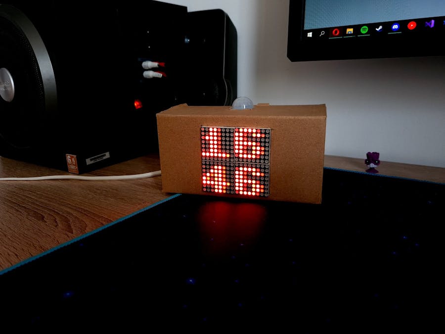
Ever hated the fact that you have to walk to the thermostat to see if the room temperature is good enough, or that you have to do 5 different swipe gestures on your phone to get to the weather app, just to find out if you need to wear a jacket or only a t-shirt when you want to go outside? This solution unifies these things into one small and fun project, where you get all the data you want at a single glance.
PresentationThe clock has two views: the "digital clock" and a "temperatures" view where it displays the current interior temperature retrieved by the DHT11 sensor and the weather at the current location parsed from the IP address of the connection (if it exists). If the clock can't parse any of the two temperatures, it will display two dashes as a placeholder.
The application also has an optional webpage that can be hosted on the Apache PHP server, and has personalization options such as custom time displaying on the screen and changing the current location of the reported weather.
The clock also makes use of a PIR sensor to only display data on the screen when it detects motion, to save energy and reduce CPU usage by delaying the routine data checks until it detects motion again.
Software requirements:- python3 - usually comes preinstalled on RPi
- Adafruit_DHT for python3 - sudo pip3 install Adafruit_Python_DHT
- RPi.GPIO for python3 - sudo apt install python3-rpi.gpio
- wpa_supplicant - for an internet connection on the RPi
Note: all the pins referenced here are BOARD-type pins, and you can connect the parts on any pins as long as you change the pin number constants in the code, so the programs work.
1. Copy the project files on your RPi, download from the linked Github repo, or copy and paste from the text boxes at the end of the document.
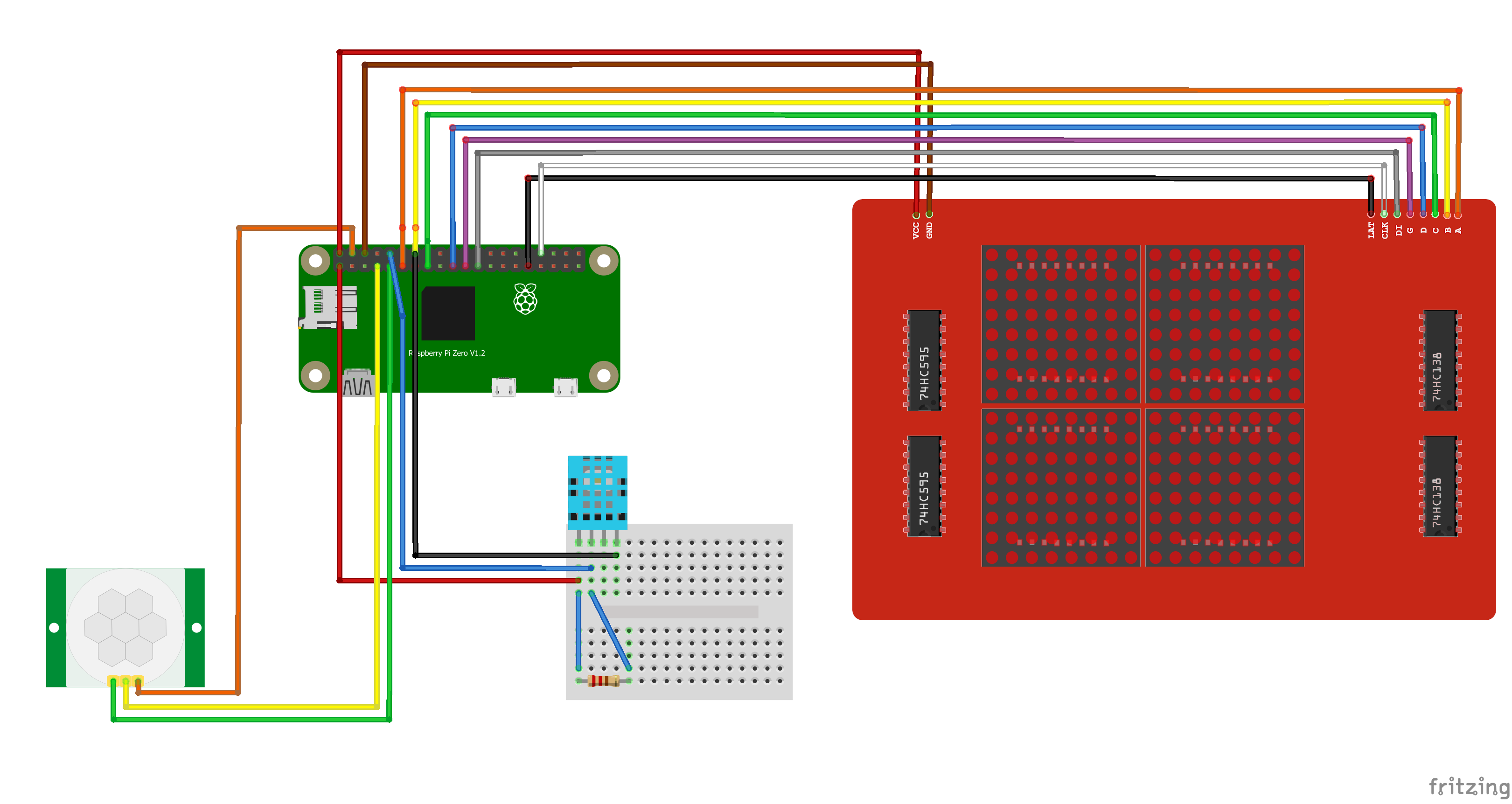
2.1. Connect the DHT11 on the breadboard with the GND on any ground pin (I used pin 14), the Signal on pin 12, and VCC on pin 1 (3.3V). We keep the other two 5V pins for the parts which require higher voltage.
2.2. Also for the DHT11 sensor on the breadboard, connect a 5kΩ or 10kΩ resistor between the VCC and the Signal pins, so the signal level stays high by default.
3. Connect the PIR Sensor with the GND on any ground pin (I used pin 9), Dout on pin 7, and VCC on a 5V power pin (I used pin 4).
4. Connect the 16x16 Matrix Display VCC pin on a 5V pin (I used pin 2), GND to any ground pin (I used 6), and the next as following: LAT CLK DI G A B C D - on pins 32, 33, 23, 21, 19, 15, 13, 11.
5. Install the required Python packages mentioned in the "Software requirements" section.
6. Run the program using the following command:
python3 main_loop.pyOptional - webpage for clock customization:
7. Install apache2 with PHP as shown here: https://howtoraspberrypi.com/how-to-install-web-server-raspberry-pi-lamp/
8. Copy the web files from the Github repo or from the textboxes at the end of this document into the /var/www/html directory.
Run the application at startupEdit the /etc/rc.local file using any text editor and add the following line before the last line which usually consists of "exit 0" and replace <PROGRAM_PATH> with the location where you copied your files:
sudo bash -c "python3 /<PROGRAM_PATH>/main_loop.py > /<PROGRAM_PATH>/watch.log 2>&1" &The "watch.log" file will store everything the program outputs.
On my system, since I moved all the program files into a directory called "watch", would be:
sudo bash -c "python3 /home/pi/watch/main_loop.py > /home/pi/watch/watch.log 2>&1" &Every component is placed in a separate module to prevent confusion, and the code is commented on almost every line so you can see better what everything does.
The first and the main process is the "main_loop.py", which manages all of the other modules, initiates instances, and specifies settings. The data which will be displayed on the screen is stored as an integer matrix of LOW and HIGH voltage values, since the screen is a LED Matrix of only one color, and the led has only two states, on or off. This module also contains code for parsing the characters so they don't overflow, or validation for cases where the requested data wasn't retrieved. Here, in an infinite while loop, there are multiple checks on whether the PIR sensor detected motion, the environment variable changed, the webpage changed settings on the used data, or if the time passed since the last check was long enough to start another routine data verification on sensors and APIs.
The second most important module, "routine.py", is called every time by the main process in a separate thread when there were changes to the configuration settings, usually changed by the webpage interface hosted by the Apache PHP server, or every 5 minutes to keep the displayed data updated. It retrieves data from the wttr.in API for the weather at the location specified in the configuration, or by the current IP address location if there's no custom setting present. Also, for time synchronization, it uses data from worldtimeapi.org. The data between the two processes is sent by using an environment variable, and the time shown on the clock is stores as a pair of system timestamp - clock timestamp, to calculate the difference between the two easier when displaying a custom time (the custom time can be set on the clock settings webpage).
The "screen.py" module is used for information display on the LED matrix screen and facilitates the sending of the signals by taking only one parameter in the "draw" function, which is the matrix we want to display. The "delay" function initially used a sleep call to the OS, but the delay received was too big (smallest was ~8ms), and so I limited myself to the option of doing nothing in a while loop for a number of cycles (it costs the CPU more but it's the only solution so that we have for a decent refresh rate on the display).
The "chars.py" module is used to store the characters in the memory for faster processing and for placing the characters into the view matrix at different positions. The letters are stored in files as a matrix of 1 and 0 values, and the file name is the character itself. There are big and small numbers, located in the "big_numbers" and "small_numbers" folders.
Reverse engineering the LED MatrixI ordered the 16x16 OKY3525-1 to have 4 times the size of the standard 8x8 matrix display, and for the serial interface which requires fewer pins to control the whole display. The surprise I got was that it came without any datasheet, instruction or schematic. So to extend the project and learn more things, I tried to get the schematic by myself. Luckily, the 4 digital circuits had the original inscription on them so I could browse the schematics to find how they work together. I attached the 2 datasheets in the "references" section.
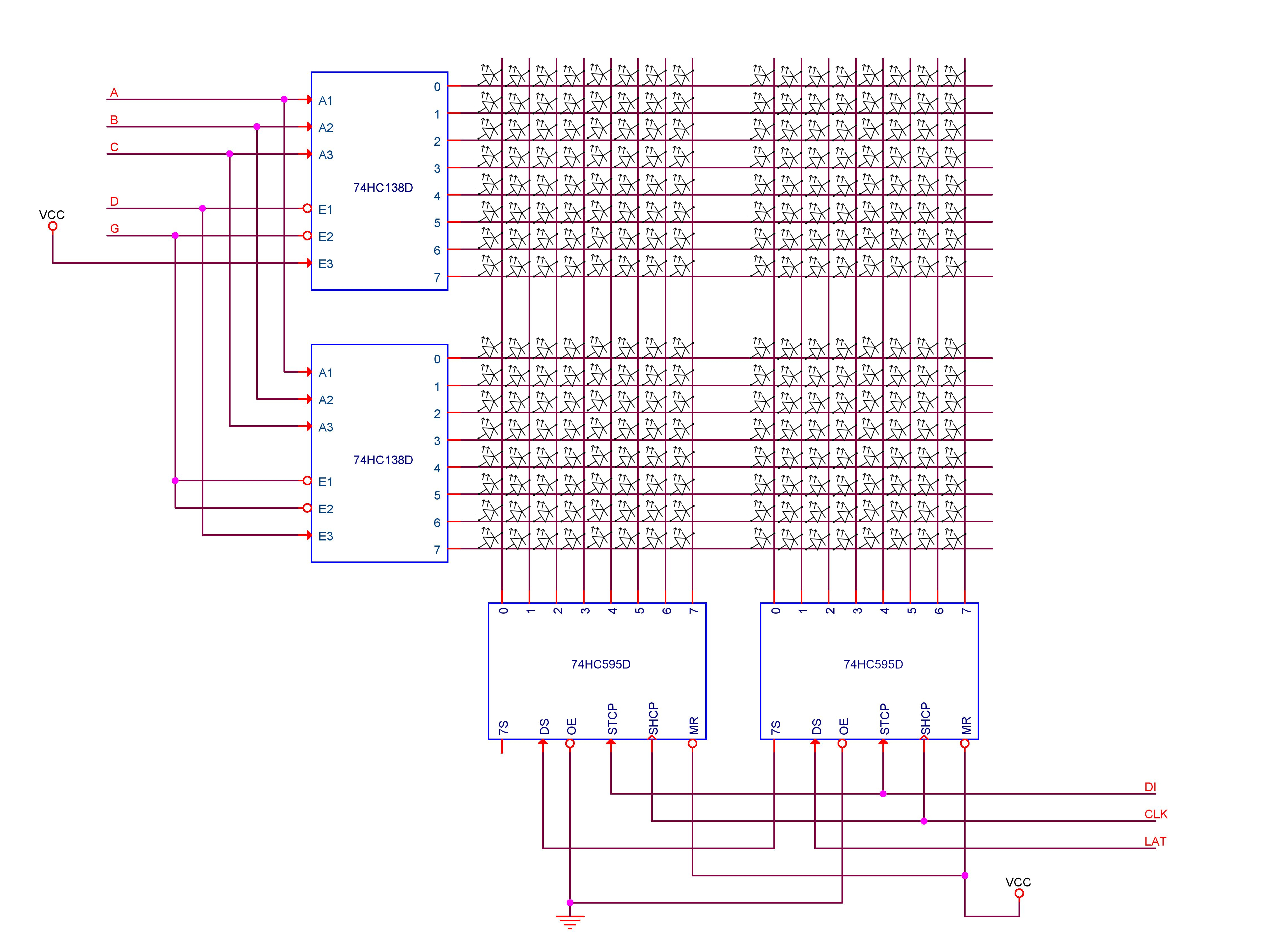
Using a multimeter and the 74HC138 datasheet, I found out that the two circuits of the same model are used for line selection, using the D, C, B and A signals (0x0000 - meaning the first line, going to 0x1111 - 16th line, which is the last). The D pin being connected to both the first and the second 74HC138, selects either one of them, so from there, the number of outputs doubles from 8 to 16 outputs. At the same time, the other two 74HC595 circuits are used for column selection on the current line using the DI, CLK and LAT signals, which confirmed to me that this display uses a D latch-type of circuit (the signals are sent and stored in the circuit, until the latch signal, when they are displayed all at once).
One thing that I didn't understand is why they chose to connect the master reset signal to VCC and output enable to GND, since these two signals give more freedom to the programmer, so the display turns the whole line off, and gives smoother transitions between the line displays.
The resulting schematic, a timing diagram (to get an example on how to send the signals) and a module for sending the correct signals to the display are attached below. I uploaded more detailed pieces of information, separately, on this Github repo.
Referenceshttps://pdf1.alldatasheet.com/datasheet-pdf/view/527976/NXP/74HC595.html
https://pdf1.alldatasheet.com/datasheet-pdf/view/650277/NXP/74HC138.html


Comments
Please log in or sign up to comment.