The lightning system used in any normal/smart home or building is still working on century old principle of ON or OFF which need to be modernize to safe energy. During day time we can use natural light to brighten up our homes/buildings but in the early morning, evening or during bad weather when less natural light is available, we have to use artificial means of light. Using current lighting systems we simply turn it ON at full power instead of complementing natural light with artificial one. And this result in waste of lot of energy which is also the biggest crisis on our planet. So in order to save energy we need to built a lightening system intelligent enough so it can complement the natural light when available, instead of simply turning on and consume maximum power.
Purposed Solution:To built energy efficient Lightening system for our smart homes/building, design intelligent smart lighting with adaptive brightness control to maximize benefit of natural light. On doing little research about such solution I have found only few IEEE research papers so far So this might be the first such solution. The biggest advantage of such system is its energy efficiency by varying the brightness and complement the natural light to maintain the adequate light.
This Idea was chosen for free hardware and it was shipped through USPS but it never arrived. The Sony Main + Ext board used in project are provided by Electromaker.IO
Library Required:u8g2: https://github.com/olikraus/u8g2
apds9930: https://github.com/Depau/APDS9930
Enabling the RTC for Arduino IDE:RTC is required to enable it for IOT platforms and enter into power save mode during night time because we don't need lots of calculation due to unavailability of external (sun) light. Initially I wasnt able to use internal RTC module of CXD5602GG mcu of SONY Spresense board using Arduino IDE but after studying its provided SDK I was amazed to find lots of useful builtin functions, sensors libraries and RTC too. Here I will request SONY team please provide some documentation on SDK and MCUs register and their functions. In order to use RTC module we need to modified the cxd56_rtc.h file in available in ...\Arduino15\packages\SPRESENSE\tools\spresense-sdk\1.1.3\spresense\release\include\sdk\ folder with given code. Also create new cxd56_rtc.c file at the same location and its code is given below.
Automatic RTC configuration using GPS:The impressive indoor performance of builtin GPS encourage me to add automatic RTC configuration feature. On start-up the GPS time variable has 1980 year value. So we can configure RTC using GPS time as soon this value changes. The RTC module needs Unix time and GPS module gives standard current time. The GPS time can be converted into Unix time using time.h library mktime() and struct tm. The code to update RTC module through GPS time is given below.
void setup_rtc(){
 if(!timeSinceEpoch){            /* check if RTC is already configured or not */
   if (Gnss.waitUpdate(-1)){     /* read GPS data */
     SpNavData NavData;
     Gnss.getNavData(&NavData);
     if (NavData.time.year!=1980){    /* check if GPS time is acquired or not */
       struct tm tm;                  /* create time struct variable */
/*
  tm_sec -> The number of seconds after the minute, normally in the range 0 to 59, but can be up to 60 to allow for leap seconds.
  tm_min -> The number of minutes after the hour, in the range 0 to 59.
  tm_hour -> The number of hours past midnight, in the range 0 to 23.
  tm_mday -> The day of the month, in the range 1 to 31.
  tm_mon -> The number of months since January, in the range 0 to 11.
  tm_year -> The number of years since 1900.
  tm_wday -> The number of days since Sunday, in the range 0 to 6.
  tm_yday -> The number of days since January 1, in the range 0 to 365.
*/
       tm.tm_year = NavData.time.year-1900;   /*Subtract 1900 from GPS time to get years since 1900 */
       tm.tm_mon = NavData.time.month-1;      /*Subtract 1 from GPS months*/
       tm.tm_mday = NavData.time.day;
       tm.tm_hour = NavData.time.hour;
       tm.tm_min = NavData.time.minute;
       tm.tm_sec = NavData.time.sec;
       timeSinceEpoch = mktime(&tm);    /* get GMT unix time */
     }
   }
   if(timeSinceEpoch){    /* Check if time is updated */
     rtcTime.tv_sec=timeSinceEpoch;    /* update the RTC module sec register */
     rtcTime.tv_nsec=0;                /* no info available to update nano sec register */
     up_rtc_settime(&rtcTime);        /* update the RTC time */
     rtc_status=true;                /* RTC status variable to ON/OFF RTC icon */
   }
 }
 else{
   rtc_status=false;
 }
}
The output of generic PIR sensor cant be used with external pull-up condition. And when interfacing it with any mcu we need to setup pin "INPUT FLOAT". In case of Sony spresense which has 1.8V VDD-IO and on its EXT. board LSF0204x 4-Bits Bidirectional Multi-Voltage Level Translator (datasheet: HERE) is used for 3.3/5V level shifting with pull-up resistor on output. So this mean every digital IO pin of J2 and J13 can not be used as floating or pull-down inputs. If we try to attach a pull-down resistor directly with EXT. board IO pin the it will make a voltage divider which is not the objective of pull-down resistor. And low level at input using pull-down can only be achieved by connecting a resistor with R<<1K.(1K pull-up resistors are used on ext. board for details please refer to EXT. board schematic documents available HERE)
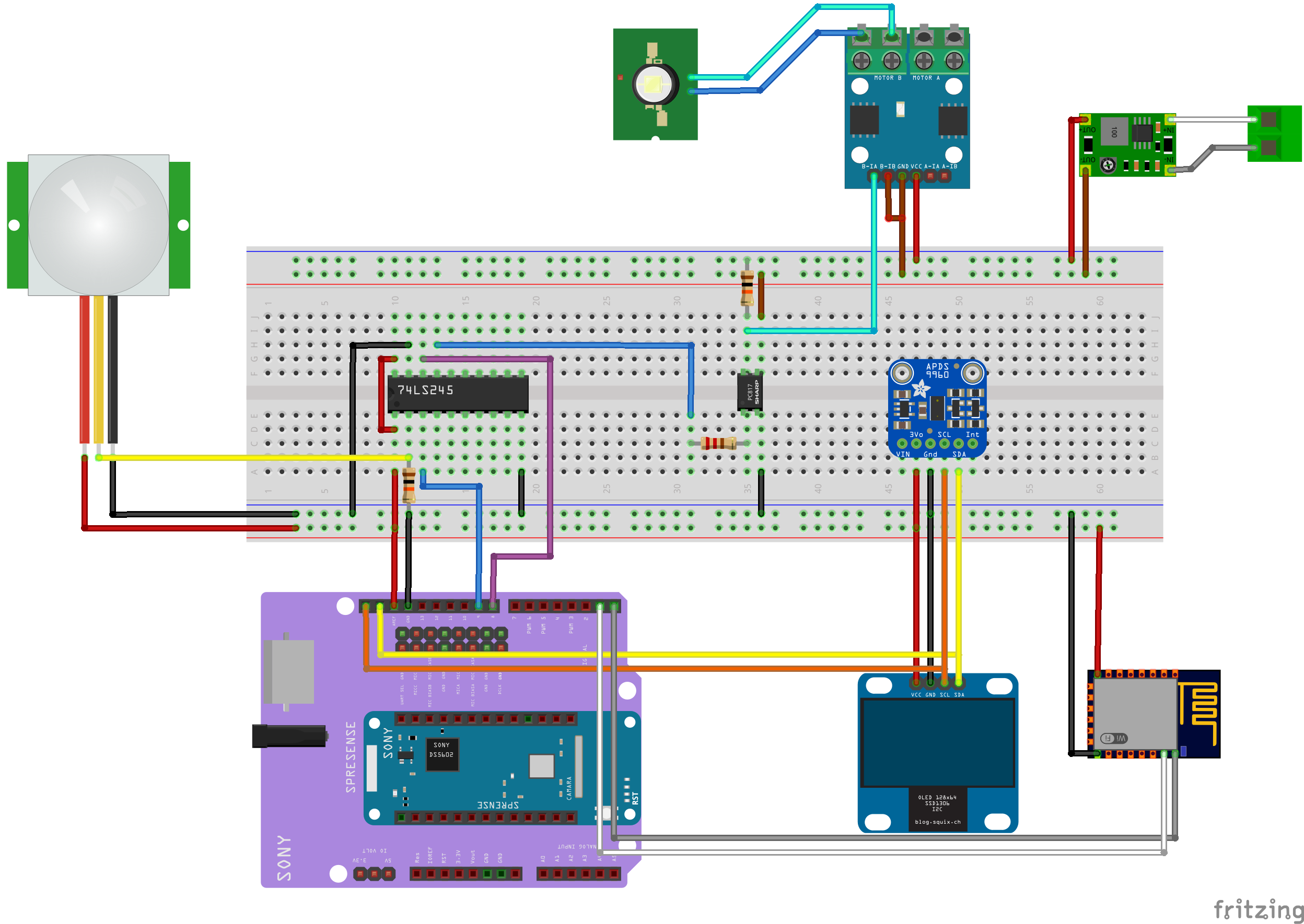
In order to overcome this problem we need to add to external buffer IC I have used 74LS245 (datasheet: HERE) as input/output buffer for PIR sensor input and LED driver pwm output (Fritzing circuit diagram).
APDS9930 Ambient light sensor:Digital ambient light sensor APDS9930 (details: HERE) is used for light intensity measurement instead of analog sensors (LDR etc) due to its ultra low power consumption and programmable interrupt feature (not used here). The module used here has onboard 5 to 3.3V LDO and I2C level shift circuit in case of 5V operation.
PIR sensor Logic:PIR sensor is set to minimum delay time and Sony external interrupt with timeout function is used to turn ON/OFF the led based on PIR sensor output. The lowest delay time setting is used to make the LED OFF delay time fully programmable. When PIR sensor module is set to minimum delay time, it gives continuously ~1 sec ON and ~1sec pulse train if any object is detected. If mcu will keep receiving pulses then LED will remain ON other wise LED can be turn OFF after user programmable delay time after last pulse received. So It can also enable us to turn OFF led as soon as (~1sec delay) we leave the room.
/* PIR senosr Input configured as external interrupt */
 pinMode(PIR_PIN, INPUT);
 attachInterrupt(PIR_PIN, pir_ISR, CHANGE);
Every time PIR interrupt is revived we update the pir_delay variable with user defined delay (seconds) variable.
/* PIR interrupt service routine */
void pir_ISR(){
  /* assign user defined delay value (seconds) to program pir delay value */
   pir_delay=pir_user_delay;
}
In our code every second, we check if pir_delay is set or not. If its set then turn on the LED and decrease the pir_delay till in become zero and turn off the LED otherwise it can be keep updating through PIR ISR. Here pir_status variable to used to display LED ON or OFF icon on OLED display.
bool pir_sw(){
 if (pir_delay>0){
   pir_status=true;
   pir_delay--;
   return true;
 }
 else{
   pir_status=false;
   return false;
 }
}
LED brightness can be digitally controlled by programmable constant current source or by applying a pwm controlled constant voltage. In this project I am using constant voltage source and pwm to adjust the LED brightness.
Turn ON voltage of Power LED (3W) that I used in this project is ~9.8V. And to generate this voltage from generic 12V power supply adapter I have used DC-DC buck convertor (also shown in pictures below). Now the second thing required to translate the Sony Spresense pwm out to LED supply pwm. After some online research I found a single supply driver IC L9110 (datasheet: HERE). Now the problem of safely driving the input pins from 3.3V voltage level of EXT. board IO boards is solved using sharp PC817 low cost opto-isolator (datasheet: HERE).
LED Driving Logic:The digital inputs of L9110 board, used in this project, are pulled up to supply voltage. So in order to turn on the output low level input is required at one of the digital IO pin. Here the permanent PULL-UP IO pins of EXT. board become very useful because LED will remain OFF until the turn ON signal is applied to it. For maximum brightness of LED (ON at full power) simply low level (0 pwm value-Arduino) input is required. And to fully turn OFF the LED high level (1023 pwm value-Arduino) input is needed.
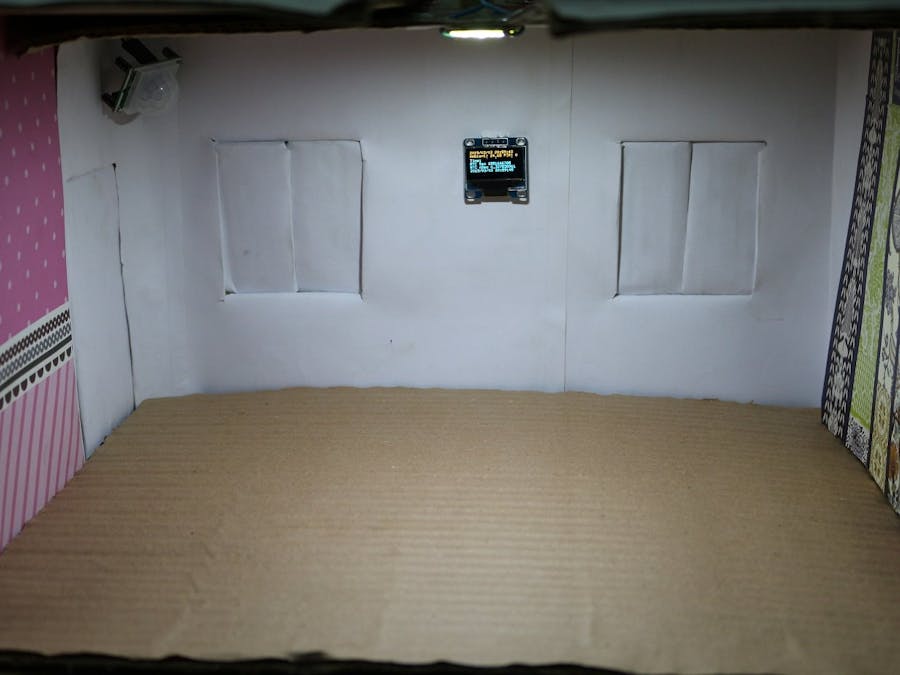
Icons for OLED display:The display module used in this project is bi-color 0.96" OLED due to its low power consumption. The display is divided in 128x16 yellow and 128x48 blue halves. The upper yellow half is used to display different icons and relative LED power consumption levels. LED on/off and successful automatic RTC configuration thorough its builtin GPS module is also showed using icons. One of the easiest way to build custom icons for OLED module is using online XBM editor (used in this project HERE).
Sony Spresense Code Optimization Issues:When u8g2 library is used with Arduino or any other board the code will compile without any problem. But on SONY board it will give ram over flow error because no code optimization flags for "gcc-arm-none-eabi" are set for compilation and linking process. And give RAM over flow code with u8g2 library.
With my limited compilers knowledge, I have tried to set the code optimization flags "-ffunction-sections, -fdata-sections" in platform.txt file of Sony Spresense (available at ...\AppData\Local\Arduino15\packages\SPRESENSE\hardware\spresense\1.1.3) but the resultant generated file didn't work for me. So I choose to modified the fonts file.
In order to over come this ram overflow error we need to modify "u8g2_fonts.c" and "u8x8_fonts.c" of u8g2 library as shown in last section.
Gallery:


Comments