Mahmood ul Hassan
Published © GPL3+

How to interface Nordic Thingy:53 with ADS1115 external ADC

Learn how to interface Nordic thingy:53 with ADS1115 an external ADC in order to read analog values.

IntermediateProtip30 minutes974
How to interface Nordic Thingy:53 with ADS1115 external ADC

Things used in this project

Hardware components

Nordic Thingy:53
Nordic Semiconductor Nordic Thingy:53
×1
J-Link EDU Mini
×1
ADS1115 module
×1
Maker Essentials - Mini Breadboards & Jumper Jerky
Pimoroni Maker Essentials - Mini Breadboards & Jumper Jerky
×1
SparkFun Breadboard - Mini
×1

Software apps and online services

nRF Connect SDK
Nordic Semiconductor nRF Connect SDK

Story

Read more

Schematics

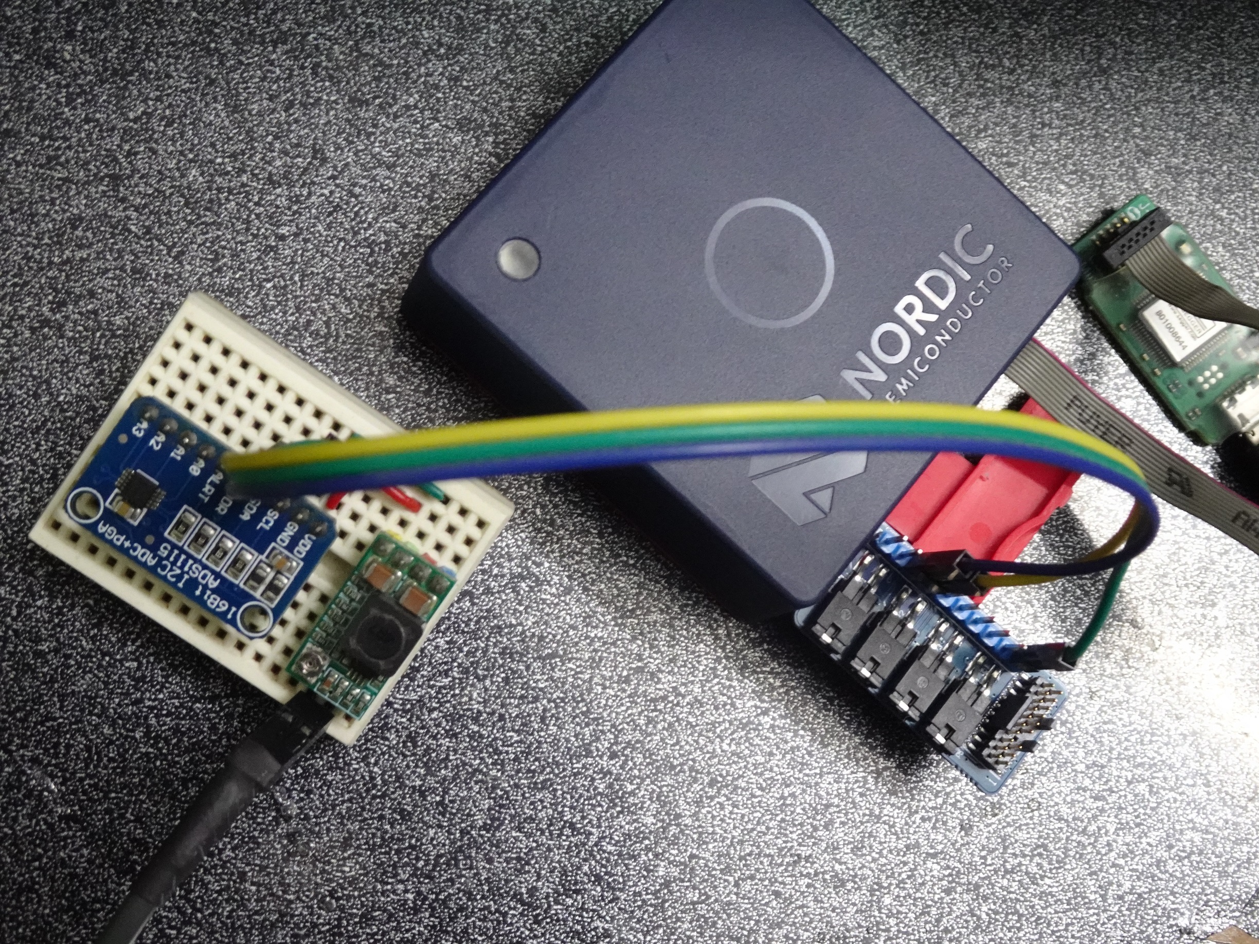
cover_5arrTWlbra.JPG

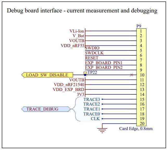
ads1115_interface_-_2_D5tm2DDZVp.JPG

Code

thingy53_nrf5340_cpuapp_ns.overlay

C/C++
Create overlay file in order to use external adc module ADS1115
// To get started, press Ctrl+Space to bring up the completion menu and view the available nodes.

// You can also use the buttons in the sidebar to perform actions on nodes.
// Actions currently available include:

// * Enabling / disabling the node
// * Adding the bus to a bus
// * Removing the node
// * Connecting ADC channels

// For more help, browse the DeviceTree documentation at https://docs.zephyrproject.org/latest/guides/dts/index.html
// You can also visit the nRF DeviceTree extension documentation at https://nrfconnect.github.io/vscode-nrf-connect/devicetree/nrfdevicetree.html

&pinctrl {
	i2c2_default: i2c2_default {
		group1 {
			psels = <NRF_PSEL(TWIM_SDA, 0, 4)>,
				<NRF_PSEL(TWIM_SCL, 0, 5)>;
		};
	};

	i2c2_sleep: i2c2_sleep {
		group1 {
			psels = <NRF_PSEL(TWIM_SDA, 0, 4)>,
				<NRF_PSEL(TWIM_SCL, 0, 5)>;
			low-power-enable;
		};
	};
};

&i2c2 {
	compatible = "nordic,nrf-twim";
	status = "okay";
	clock-frequency = <I2C_BITRATE_STANDARD>;

	pinctrl-0 = <&i2c2_default>;
	pinctrl-1 = <&i2c2_sleep>;
	pinctrl-names = "default", "sleep";

	ads1115: ads1115@48 {
		compatible = "ti,ads1115";
		#io-channel-cells = <1>;
		reg = <0x48 >;
		label = "ADS1115";
	};
};

main.c

C/C++
/*
 * Copyright (c) 2012-2014 Wind River Systems, Inc.
 *
 * SPDX-License-Identifier: Apache-2.0
 */

#include <zephyr/zephyr.h>
#include <zephyr/drivers/sensor.h>
#include <zephyr/drivers/i2c.h>
#include "ads1115.h"

ADS1115 ads1115;

void main(void)
{
	printk("ADS1115 Example Thingy:53! %s\n", CONFIG_BOARD);

	ADS1115_init(&ads1115);

	while(1){
		k_sleep(K_MSEC(1000));

		printf("ADC_0: %0.2f | ADC_1: %0.2f | ADC_2: %0.2f | ADC_3: %0.2f\n", \ 
		ADS1115_readADC(&ads1115, CH_0), \
		ADS1115_readADC(&ads1115, CH_1), \
		ADS1115_readADC(&ads1115, CH_2), \
		ADS1115_readADC(&ads1115, CH_3));
	}
}

ads1115.c

C/C++
this file can be place in any folder and build successfully but only after making the required changes in CMakeLists.txt file.
/*!
 * @file ads1115.c
 *
 * twitter: @ArduinoEasy
 */

#include "ads1115.h"
#include <zephyr/zephyr.h>
#include <zephyr/drivers/i2c.h>

#define ADS_NODE DT_NODELABEL(ads1115)
static const struct i2c_dt_spec ads_i2c = I2C_DT_SPEC_GET(ADS_NODE);

uint8_t ads1115_txBuff[3];
uint8_t ads1115_rxBuff[2];

static void ADS1115_WriteRegister(ADS1115 *ads1115_module, uint8_t reg, uint16_t value);
static int16_t ADS1115_ReadRegister(ADS1115 *ads1115_module, uint8_t reg);
static float get_lsb_multiplier(adsGain_t gain);
//static uint32_t get_delay_usec(adsSPS_t sps);
static uint32_t get_delay_msec(adsSPS_t sps);
static uint16_t get_adc_config(ADS1115 *ads1115_module);

void ADS1115_WriteRegister (ADS1115 *ads1115_module, uint8_t reg, uint16_t value){
//	uint8_t data[3];
	ads1115_txBuff[0] = reg;
	ads1115_txBuff[1] = (value >> 8);
	ads1115_txBuff[2] = (value & 0xFF);

  i2c_write_dt(&ads_i2c,ads1115_txBuff,3);
}

int16_t ADS1115_ReadRegister(ADS1115 *ads1115_module, uint8_t reg){
//	uint8_t data[2];
	ads1115_txBuff[0] = reg;

  i2c_write_dt(&ads_i2c,ads1115_txBuff,1);
  i2c_read_dt(&ads_i2c,ads1115_rxBuff,2);

	return (ads1115_rxBuff[0] << 8) | ads1115_rxBuff[1];
}

float get_lsb_multiplier(adsGain_t gain){
	float lsb_multiplier=0;
  switch (gain) {
  case (GAIN_TWOTHIRDS):
    lsb_multiplier = 0.1875;
    break;
  case (GAIN_ONE):
    lsb_multiplier = 0.125;
    break;
  case (GAIN_TWO):
    lsb_multiplier = 0.0625;
    break;
  case (GAIN_FOUR):
    lsb_multiplier = 0.03125;
    break;
  case (GAIN_EIGHT):
    lsb_multiplier = 0.015625;
    break;
  case (GAIN_SIXTEEN):
    lsb_multiplier = 0.0078125;
    break;
	default:
    lsb_multiplier = 0.0625;
    break;
  }
	return lsb_multiplier;
}

/*
uint32_t get_delay_usec(adsSPS_t sps){
	uint32_t delay = 0;
  switch (sps) {
  case (SPS_8):
    delay = 125000;
    break;
  case (SPS_16):
    delay = 62500;
    break;
  case (SPS_32):
    delay = 31250;
    break;
  case (SPS_64):
    delay = 15625;
    break;
  case (SPS_128):
    delay = 7825;
    break;
  case (SPS_250):
    delay = 4000;
    break;
  case (SPS_475):
    delay = 2150;
    break;
  case (SPS_860):
    delay = 1200;
    break;
	default:
    delay = 7825;
    break;
  }
	return delay;
}
*/
uint32_t get_delay_msec(adsSPS_t sps){
	uint32_t delay = 0;
  switch (sps) {
  case (SPS_8):
    delay = 125;
    break;
  case (SPS_16):
    delay = 63;
    break;
  case (SPS_32):
    delay = 32;
    break;
  case (SPS_64):
    delay = 16;
    break;
  case (SPS_128):
    delay = 8;
    break;
  case (SPS_250):
    delay = 4;
    break;
  case (SPS_475):
    delay = 3;
    break;
  case (SPS_860):
    delay = 2;
    break;
	default:
    delay = 8;
    break;
  }
	return delay;
}

uint16_t get_adc_config(ADS1115 *ads1115_module){
	ads1115_module->m_conversionDelay = get_delay_msec(ads1115_module->m_samplingRate);
	ads1115_module->m_lsbMultiplier = get_lsb_multiplier(ads1115_module->m_gain)/1000;

  return
      ADS1115_REG_CONFIG_CQUE_NONE |    // Disable the comparator (default val)
      ADS1115_REG_CONFIG_CLAT_NONLAT |  // Non-latching (default val)
      ADS1115_REG_CONFIG_CPOL_ACTVLOW | // Alert/Rdy active low   (default val)
      ads1115_module->m_compMode |							// Comparator Mode
      ads1115_module->m_samplingRate |					// Sampling Rate
      ads1115_module->m_gain |									// PGA Gain
      ads1115_module->m_mode;									// ADC mode
}

/**************************************************************************/
/*!
    @brief  Instantiates a new ADS1115 struct w/appropriate properties
    @param  Device struct
*/
/**************************************************************************/
void ADS1115_init(ADS1115 *ads1115_module){
	// Start with default values
	ads1115_module->m_samplingRate = SPS_128;							// 128 samples per second (default)
	ads1115_module->m_mode 		= ADS1115_REG_CONFIG_MODE_SINGLE;	// Single-shot mode (default)
	ads1115_module->m_gain 		= GAIN_TWOTHIRDS;					// +/- 6.144V range (limited to VDD +0.3V max!)
	ads1115_module->m_compMode 	= CMODE_TRAD;						// Traditional comparator (default val)

  ads1115_module->config =
      ADS1115_REG_CONFIG_CQUE_NONE |    // Disable the comparator (default val)
      ADS1115_REG_CONFIG_CLAT_NONLAT |  // Non-latching (default val)
      ADS1115_REG_CONFIG_CPOL_ACTVLOW | // Alert/Rdy active low   (default val)
      ads1115_module->m_compMode |				// Comparator Mode
      ads1115_module->m_samplingRate |			// Sampling Rate
      ads1115_module->m_gain |					// PGA Gain
      ads1115_module->m_mode;					// ADC mode

	ads1115_module->m_conversionDelay = (uint8_t)ADS1115_CONVERSIONDELAY;
}

/**************************************************************************/
/*!
    @brief  Reset a ADS1115
    @param  Device struct
*/
/**************************************************************************/
void ADS1115_reset(ADS1115 *ads1115_module){
//	uint8_t cmd = 0x06;
	ads1115_txBuff[0] = 0x06;

i2c_write_dt(&ads_i2c,ads1115_txBuff,1);
}

/**************************************************************************/
/*!
    @brief  Sets the gain and input voltage range
    @param gain gain setting to use
*/
/**************************************************************************/
void ADS1115_setGain(ADS1115 *ads1115_module, adsGain_t gain){
	ads1115_module->m_gain = gain;
}

/**************************************************************************/
/*!
    @brief  Gets a gain and input voltage range
    @return the gain setting
*/
/**************************************************************************/
adsGain_t ADS1115_getGain(ADS1115 *ads1115_module){
	return ads1115_module->m_gain;
}

/**************************************************************************/
/*!
    @brief  Sets the Sampling rate
		@param  sps: sampling rate to use
*/
/**************************************************************************/
void ADS1115_setSPS(ADS1115 *ads1115_module, adsSPS_t sps){
	ads1115_module->m_samplingRate = sps;
}

/**************************************************************************/
/*!
    @brief  Gets the Sampling rate
    @return the sampling rate
*/
/**************************************************************************/
adsSPS_t ADS1115_getSPS(ADS1115 *ads1115_module){
	return ads1115_module->m_samplingRate;
}

/**************************************************************************/
/*!
    @brief  Sets a ADC conversion mode setting
    @param  mode
*/
/**************************************************************************/
void ADS1115_setCONV(ADS1115 *ads1115_module, adsCONV_t mode){
	ads1115_module->m_mode = mode;
}

/**************************************************************************/
/*!
    @brief  Gets a ADC conversion mode setting
    @return the conversion setting
*/
/**************************************************************************/
adsCONV_t ADS1115_getCONV(ADS1115 *ads1115_module){
	return ads1115_module->m_mode;
}

/**************************************************************************/
/*!
    @brief  Gets a single-ended ADC reading from the specified channel
    @param channel ADC channel to read
    @return the ADC reading
*/
/**************************************************************************/
float ADS1115_readADC(ADS1115 *ads1115_module, adc_Ch_t channel){
  if ((channel & ~ADS1115_REG_CONFIG_MUX_MASK) != 0) {
    return 0;
  }

  uint16_t config = get_adc_config(ads1115_module);;
	config |= channel;
  config |= ADS1115_REG_CONFIG_OS_SINGLE;

	ads1115_module->config = config;

	uint16_t ret_val;
	do{
		ret_val = ADS1115_ReadRegister(ads1115_module, ADS1115_REG_POINTER_CONFIG);
	}
	while( (ret_val & ADS1115_REG_CONFIG_OS_MASK) == ADS1115_REG_CONFIG_OS_BUSY);

	do{
		ADS1115_WriteRegister(ads1115_module, ADS1115_REG_POINTER_CONFIG, config);
		ret_val = ADS1115_ReadRegister(ads1115_module, ADS1115_REG_POINTER_CONFIG);
	}while( (ret_val & ADS1115_REG_CONFIG_MUX_MASK) != (config & ADS1115_REG_CONFIG_MUX_MASK) );

	k_sleep(K_MSEC(ads1115_module->m_conversionDelay));

	do{
		ret_val = ADS1115_ReadRegister(ads1115_module, ADS1115_REG_POINTER_CONFIG);
	}
	while( (ret_val & ADS1115_REG_CONFIG_OS_MASK) == ADS1115_REG_CONFIG_OS_BUSY);

	if(channel>ADS1115_REG_CONFIG_MUX_DIFF_2_3)
		return (float)abs(ADS1115_ReadRegister(ads1115_module, ADS1115_REG_POINTER_CONVERT)) * ads1115_module->m_lsbMultiplier;
	else
		return (float)ADS1115_ReadRegister(ads1115_module, ADS1115_REG_POINTER_CONVERT) * ads1115_module->m_lsbMultiplier;
}

/**************************************************************************/
/*!
    @brief  Gets a single-ended ADC reading from the specified channel
    @param channel ADC channel to read
    @return the ADC reading
*/
/**************************************************************************/
int16_t ADS1115_readADC_raw(ADS1115 *ads1115_module, adc_Ch_t channel){

  if ((channel & ~ADS1115_REG_CONFIG_MUX_MASK) != 0) {
    return 0;
  }

  uint16_t config = get_adc_config(ads1115_module);;
	config |= channel;
  config |= ADS1115_REG_CONFIG_OS_SINGLE;

	ads1115_module->config = config;

	uint16_t ret_val = ADS1115_REG_CONFIG_OS_BUSY;
	do{
		ret_val = ADS1115_ReadRegister(ads1115_module, ADS1115_REG_POINTER_CONFIG);
	}
	while( (ret_val & ADS1115_REG_CONFIG_OS_MASK) == ADS1115_REG_CONFIG_OS_BUSY);

	do{
		ADS1115_WriteRegister(ads1115_module, ADS1115_REG_POINTER_CONFIG, config);
		ret_val = ADS1115_ReadRegister(ads1115_module, ADS1115_REG_POINTER_CONFIG);
	}while( (ret_val & ADS1115_REG_CONFIG_MUX_MASK) != (config & ADS1115_REG_CONFIG_MUX_MASK) );

  k_sleep(K_MSEC(ads1115_module->m_conversionDelay));

	do{
		ret_val = ADS1115_ReadRegister(ads1115_module, ADS1115_REG_POINTER_CONFIG);
	}
	while( (ret_val & ADS1115_REG_CONFIG_OS_MASK) == ADS1115_REG_CONFIG_OS_BUSY);

	return ADS1115_ReadRegister(ads1115_module, ADS1115_REG_POINTER_CONVERT);
}

/**************************************************************************/
/*!
    @brief  Sets up the comparator to operate in basic mode, causing the
            ALERT/RDY pin to assert (go from high to low) when the ADC
            value exceeds the specified threshold.
            This will also set the ADC in continuous conversion mode.
    @param channel ADC channel to use
    @param threshold comparator threshold
*/
/**************************************************************************/
void ADS1115_startComparator_SingleEnded(ADS1115 *ads1115_module, uint8_t channel, int16_t threshold){
	// Start with default values
  uint16_t config =
      ADS1115_REG_CONFIG_CQUE_1CONV |   // Comparator enabled and asserts on 1 match
      ADS1115_REG_CONFIG_CLAT_LATCH |   // Latching mode
      ADS1115_REG_CONFIG_CPOL_ACTVLOW | // Alert/Rdy active low   (default val)
      ads1115_module->m_compMode |							// Comparator Mode
      ads1115_module->m_samplingRate |					// Sampling Rate
			ads1115_module->m_gain |									// ADC gain setting
      ADS1115_REG_CONFIG_MODE_CONTIN;   // Continuous conversion mode

  // Set single-ended input channel
  switch (channel) {
  case (0):
    config |= ADS1115_REG_CONFIG_MUX_SINGLE_0;
    break;
  case (1):
    config |= ADS1115_REG_CONFIG_MUX_SINGLE_1;
    break;
  case (2):
    config |= ADS1115_REG_CONFIG_MUX_SINGLE_2;
    break;
  case (3):
    config |= ADS1115_REG_CONFIG_MUX_SINGLE_3;
    break;
  }

	ads1115_module->config = config;

  // Set the high threshold register
	ADS1115_WriteRegister(ads1115_module, ADS1115_REG_POINTER_HITHRESH, threshold);

  // Write config register to the ADC
  ADS1115_WriteRegister(ads1115_module, ADS1115_REG_POINTER_CONFIG, config);
}

/**************************************************************************/
/*!
    @brief  In order to clear the comparator, we need to read the
            conversion results.  This function reads the last conversion
            results without changing the config value.
    @return the last ADC reading
*/
/**************************************************************************/
float ADS1115_getLastConversionResults(ADS1115 *ads1115_module){
	uint16_t ret_val = ADS1115_REG_CONFIG_OS_BUSY;
  // Wait for the conversion to complete
  k_sleep(K_MSEC(ads1115_module->m_conversionDelay));
	do{
		ret_val = ADS1115_ReadRegister(ads1115_module, ADS1115_REG_POINTER_CONFIG);
	}
	while( (ret_val & ADS1115_REG_CONFIG_OS_MASK) == ADS1115_REG_CONFIG_OS_BUSY);

  // Read the conversion results
	return (float)ADS1115_ReadRegister(ads1115_module, ADS1115_REG_POINTER_CONVERT) * ads1115_module->m_lsbMultiplier;
}

/************************************************************************/

ads1115.h

C/C++
this file can be place in any folder and build successfully but only after making the required changes in CMakeLists.txt file.
/*
 * ads1115.h
 * twitter: @ArduinoEasy
 *
 */

#ifndef ADS1115_H_
#define ADS1115_H_

#include <stdbool.h>
#include <stdint.h>

/*=========================================================================
    I2C ADDRESS/BITS
    -----------------------------------------------------------------------*/
#define ADS1115_ADDRESS (0x48) ///< 100 1000 (ADDR = GND)
/*=========================================================================*/

/*=========================================================================
    CONVERSION DELAY (in mS)
    -----------------------------------------------------------------------*/
//#define ADS1115_CONVERSIONDELAY (1165) ///< Minimum Conversion Delay: usec ( Maximum Sample Rate: 860 SPS )
#define ADS1115_CONVERSIONDELAY (2) ///< Minimum Conversion Delay: msec ( Maximum Sample Rate: 860 SPS )
/*=========================================================================*/

/*=========================================================================
    POINTER REGISTER
    -----------------------------------------------------------------------*/
#define ADS1115_REG_POINTER_MASK		  (0x03)	///< Point mask
#define ADS1115_REG_POINTER_CONVERT		(0x00)	///< Conversion
#define ADS1115_REG_POINTER_CONFIG		(0x01)	///< Configuration
#define ADS1115_REG_POINTER_LOWTHRESH	(0x02)	///< Low threshold
#define ADS1115_REG_POINTER_HITHRESH	(0x03)	///< High threshold
/*=========================================================================*/

/*=========================================================================
    CONFIG REGISTER
    -----------------------------------------------------------------------*/
#define ADS1115_REG_CONFIG_OS_MASK		(0x8000) ///< OS Mask
#define ADS1115_REG_CONFIG_OS_SINGLE	(0x8000) ///< Write: Set to start a single-conversion
#define ADS1115_REG_CONFIG_OS_BUSY		(0x0000) ///< Read: Bit = 0 when conversion is in progress
#define ADS1115_REG_CONFIG_OS_NOTBUSY	(0x8000) ///< Read: Bit = 1 when device is not performing a conversion

#define ADS1115_REG_CONFIG_MUX_MASK 	  (0x7000) ///< Mux Mask
#define ADS1115_REG_CONFIG_MUX_DIFF_0_1	(0x0000) ///< Differential P = AIN0, N = AIN1 (default)
#define ADS1115_REG_CONFIG_MUX_DIFF_0_3	(0x1000) ///< Differential P = AIN0, N = AIN3
#define ADS1115_REG_CONFIG_MUX_DIFF_1_3	(0x2000) ///< Differential P = AIN1, N = AIN3
#define ADS1115_REG_CONFIG_MUX_DIFF_2_3	(0x3000) ///< Differential P = AIN2, N = AIN3

#define ADS1115_REG_CONFIG_MUX_SINGLE_0 (0x4000) ///< Single-ended AIN0
#define ADS1115_REG_CONFIG_MUX_SINGLE_1 (0x5000) ///< Single-ended AIN1
#define ADS1115_REG_CONFIG_MUX_SINGLE_2 (0x6000) ///< Single-ended AIN2
#define ADS1115_REG_CONFIG_MUX_SINGLE_3 (0x7000) ///< Single-ended AIN3


// The ADC input range (or gain) can be changed via the following
// functions, but be careful never to exceed VDD +0.3V max, or to
// exceed the upper and lower limits if you adjust the input range!
// Setting these values incorrectly may destroy your ADC!
//                                                                							ADS1115
//                                                                							-------
// ADS1115_setGain(&adc1115, GAIN_TWOTHIRDS);  // 2/3x gain +/- 6.144V  1 bit = 0.1875mV
// ADS1115_setGain(&adc1115, GAIN_ONE);        // 1x gain   +/- 4.096V  1 bit = 0.125mV
// ADS1115_setGain(&adc1115, GAIN_TWO);        // 2x gain   +/- 2.048V  1 bit = 0.0625mV	(default)
// ADS1115_setGain(&adc1115, GAIN_FOUR);       // 4x gain   +/- 1.024V  1 bit = 0.03125mV
// ADS1115_setGain(&adc1115, GAIN_EIGHT);      // 8x gain   +/- 0.512V  1 bit = 0.015625mV
// ADS1115_setGain(&adc1115, GAIN_SIXTEEN);    // 16x gain  +/- 0.256V  1 bit = 0.0078125mV

#define ADS1115_REG_CONFIG_PGA_MASK		  (0x0E00) ///< PGA Mask
#define ADS1115_REG_CONFIG_PGA_6_144V 	(0x0000) ///< +/-6.144V range = Gain 2/3
#define ADS1115_REG_CONFIG_PGA_4_096V 	(0x0200) ///< +/-4.096V range = Gain 1
#define ADS1115_REG_CONFIG_PGA_2_048V	  (0x0400) ///< +/-2.048V range = Gain 2 (default)
#define ADS1115_REG_CONFIG_PGA_1_024V 	(0x0600) ///< +/-1.024V range = Gain 4
#define ADS1115_REG_CONFIG_PGA_0_512V 	(0x0800) ///< +/-0.512V range = Gain 8
#define ADS1115_REG_CONFIG_PGA_0_256V 	(0x0A00) ///< +/-0.256V range = Gain 16

#define ADS1115_REG_CONFIG_MODE_MASK	  (0x0100)   ///< Mode Mask
#define ADS1115_REG_CONFIG_MODE_CONTIN	(0x0000) ///< Continuous conversion mode
#define ADS1115_REG_CONFIG_MODE_SINGLE	(0x0100) ///< Power-down single-shot mode (default)

#define ADS1115_REG_CONFIG_DR_MASK		(0x00E0)	///< Data Rate Mask
#define ADS1115_REG_CONFIG_DR_8SPS		(0x0000)	///< 8 samples per second
#define ADS1115_REG_CONFIG_DR_16SPS		(0x0020)	///< 16 samples per second
#define ADS1115_REG_CONFIG_DR_32SPS		(0x0040)	///< 32 samples per second
#define ADS1115_REG_CONFIG_DR_64SPS		(0x0060)	///< 64 samples per second
#define ADS1115_REG_CONFIG_DR_128SPS	(0x0080)	///< 128 samples per second (default)
#define ADS1115_REG_CONFIG_DR_250SPS	(0x00A0)	///< 250 samples per second
#define ADS1115_REG_CONFIG_DR_475SPS	(0x00C0)	///< 475 samples per second
#define ADS1115_REG_CONFIG_DR_860SPS	(0x00E0)	///< 860 samples per second

#define ADS1115_REG_CONFIG_CMODE_MASK 	(0x0010) ///< CMode Mask
#define ADS1115_REG_CONFIG_CMODE_TRAD 	(0x0000) ///< Traditional comparator with hysteresis (default)
#define ADS1115_REG_CONFIG_CMODE_WINDOW (0x0010) ///< Window comparator

#define ADS1115_REG_CONFIG_CPOL_MASK	  (0x0008) ///< CPol Mask
#define ADS1115_REG_CONFIG_CPOL_ACTVLOW	(0x0000) ///< ALERT/RDY pin is low when active (default)
#define ADS1115_REG_CONFIG_CPOL_ACTVHI	(0x0008) ///< ALERT/RDY pin is high when active

#define ADS1115_REG_CONFIG_CLAT_MASK	  (0x0004) ///< Determines if ALERT/RDY pin latches once asserted
#define ADS1115_REG_CONFIG_CLAT_NONLAT	(0x0000) ///< Non-latching comparator (default)
#define ADS1115_REG_CONFIG_CLAT_LATCH	  (0x0004) ///< Latching comparator

#define ADS1115_REG_CONFIG_CQUE_MASK	(0x0003) ///< CQue Mask
#define ADS1115_REG_CONFIG_CQUE_1CONV	(0x0000) ///< Assert ALERT/RDY after one conversions
#define ADS1115_REG_CONFIG_CQUE_2CONV	(0x0001) ///< Assert ALERT/RDY after two conversions
#define ADS1115_REG_CONFIG_CQUE_4CONV	(0x0002) ///< Assert ALERT/RDY after four conversions
#define ADS1115_REG_CONFIG_CQUE_NONE	(0x0003) ///< Disable the comparator and put ALERT/RDY in high state (default)
/*=========================================================================*/

/** Gain settings */
typedef enum {
  GAIN_TWOTHIRDS = ADS1115_REG_CONFIG_PGA_6_144V,
  GAIN_ONE 			 = ADS1115_REG_CONFIG_PGA_4_096V,
  GAIN_TWO 			 = ADS1115_REG_CONFIG_PGA_2_048V,
  GAIN_FOUR			 = ADS1115_REG_CONFIG_PGA_1_024V,
  GAIN_EIGHT		 = ADS1115_REG_CONFIG_PGA_0_512V,
  GAIN_SIXTEEN	 = ADS1115_REG_CONFIG_PGA_0_256V
} adsGain_t;

/** Sampling settings */
typedef enum {
  SPS_8 	= ADS1115_REG_CONFIG_DR_8SPS,
  SPS_16 	= ADS1115_REG_CONFIG_DR_16SPS,
  SPS_32	= ADS1115_REG_CONFIG_DR_32SPS,
  SPS_64	= ADS1115_REG_CONFIG_DR_64SPS,
  SPS_128	= ADS1115_REG_CONFIG_DR_128SPS,
  SPS_250	= ADS1115_REG_CONFIG_DR_250SPS,
  SPS_475	= ADS1115_REG_CONFIG_DR_475SPS,
  SPS_860 = ADS1115_REG_CONFIG_DR_860SPS
} adsSPS_t;

/** Comparator Mode */
typedef enum {
  CMODE_TRAD 	= ADS1115_REG_CONFIG_CMODE_TRAD,
  CMODE_WINDOW 	= ADS1115_REG_CONFIG_CMODE_WINDOW
} adsCMODE_t;

/** Conversion Mode */
typedef enum {
  SINGLE_CONV	= ADS1115_REG_CONFIG_MODE_SINGLE,
  CONT_CONV		= ADS1115_REG_CONFIG_MODE_CONTIN
} adsCONV_t;

/** ADC channels */
typedef enum {
	CH_0	= ADS1115_REG_CONFIG_MUX_SINGLE_0,
	CH_1	= ADS1115_REG_CONFIG_MUX_SINGLE_1,
	CH_2	= ADS1115_REG_CONFIG_MUX_SINGLE_2,
	CH_3	= ADS1115_REG_CONFIG_MUX_SINGLE_3,

  DIFF_0_1 = ADS1115_REG_CONFIG_MUX_DIFF_0_1,
  DIFF_0_3 = ADS1115_REG_CONFIG_MUX_DIFF_0_3,
  DIFF_1_3 = ADS1115_REG_CONFIG_MUX_DIFF_1_3,
  DIFF_2_3 = ADS1115_REG_CONFIG_MUX_DIFF_2_3
} adc_Ch_t;

/**************************************************************************/
/*!
    @brief  Sensor driver for the Adafruit ADS1115 ADC breakout.
*/
/**************************************************************************/

/*	Structure to store address and settings of ADS1115 16-bit ADC IC	*/
typedef struct
{
	// Instance-specific properties
	uint16_t		config;					    //< ADC config
	uint16_t		m_samplingRate; 		//< sampling rate
	uint16_t		m_mode; 				    //< ADC mode
	uint32_t		m_conversionDelay;	//< conversion deay
	adsGain_t		m_gain;					    //< ADC gain
	uint16_t		m_compMode;				  //< Comparator Mode
	float			  m_lsbMultiplier;		//< LSB multiplier
	uint16_t		Hi_thresh;				  //< High Threshold value
	uint16_t		Lo_thresh;				  //< Low Threshold value
}ADS1115;


void ADS1115_reset(ADS1115 *ads1115_module);

void ADS1115_init(ADS1115 *ads1115_module);

float ADS1115_readADC(ADS1115 *ads1115_module, adc_Ch_t channel);
int16_t ADS1115_readADC_raw(ADS1115 *ads1115_module, adc_Ch_t channel);

void ADS1115_startComparator_SingleEnded(ADS1115 *ads1115_module, uint8_t channel, int16_t threshold);

float ADS1115_getLastConversionResults(ADS1115 *ads1115_module);

void ADS1115_setGain(ADS1115 *ads1115_module, adsGain_t gain);
adsGain_t ADS1115_getGain(ADS1115 *ads1115_module);

void ADS1115_setSPS(ADS1115 *ads1115_module, adsSPS_t sps);
adsSPS_t ADS1115_getSPS(ADS1115 *ads1115_module);

void ADS1115_setCONV(ADS1115 *ads1115_module, adsCONV_t sps);
adsCONV_t ADS1115_getCONV(ADS1115 *ads1115_module);

#endif /* ADS1115_H_ */

Credits

Mahmood ul Hassan
13 projects • 18 followers
Electronics Engineer with more than 13 years of experience in reverse engineering and test & measurement equipment designing

Comments