


Hardware components | ||||||
 |
| × | 1 | |||
 |
| × | 1 | |||
 |
| × | 1 | |||
 |
| × | 1 | |||
 |
| × | 1 | |||
Hello,
In this tutorial, we'll try to demonstrate how to build fundamental CanSat electronics using a Cmod A7 FPGA board.
CanSat (Can Sized Satellite) is a type of satellite that is used for mostly educational purposes. There are several competitions around the world, in the area of aerospace, with the main goal to teach flight. CanSat operations are similar to those of micro or bigger size satellites. In this tutorial we will explain why we chose FPGA as the main computer of our CanSat as well as the development stages of the project.
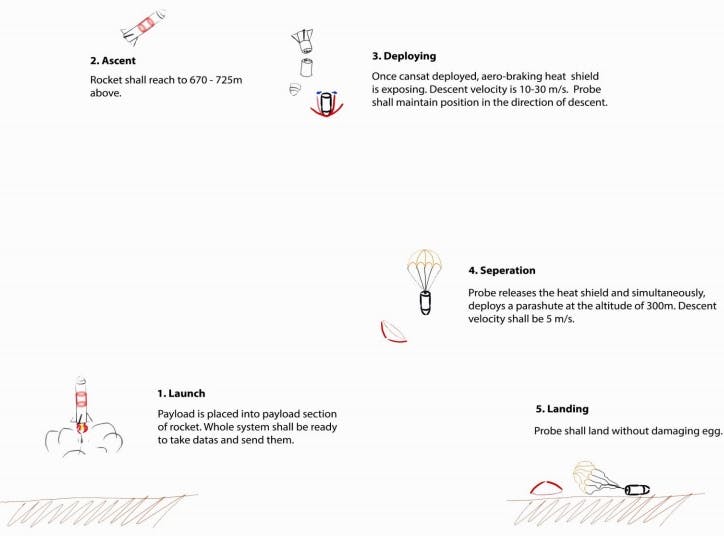
First, the main reason to chose the FPGA board is, of course, the high speed capability. CanSats have specific missions such as carrying and keeping an egg intact during the whole flight. They are launched by a rocket and deployed at an altitude of roughly 1km. After deployment from a rocket, CanSat start to collect telemetry data such as atmospheric pressure, air temperature, wind speed, GPS coordinates and so on. At the same time, the collected telemetry is being transmitted to a ground station to be observed. CanSat primarily consists of two parts: a payload which operates missions and a container which protects the payload during hard launch and deployment phases. CanSat is separated into two parts after rocket deployment and the two parts continue their descent separately. Below is a simple illustration of the operations.
Step 1: Components & Software Tools UsedElectronics Components
- Cmod A7 FPGA Board
- PmodGPS
- PmodNav IMU sensor
- PmodTmp2 Precise Thermometer
- QS12 mini Camera
- Buzzer
- XBee Pro XSC RF modules
Software Tools
- Vivado
- Vivado SDK for programming IP cores
- Verilog
- C
- XCTU XBee programming interface
- QT GUI design Interface
- C++
The CanSat is responsible for collecting telemetry data every second, creating a telemetry frame and sending data to our ground station periodically.
There is a laptop in our ground station which receives telemetry data using XBee RF modules and a high gain Yagi antenna and plots in real time. The software in the ground station for receiving the incoming telemetry data was developed in QT GUI design tool using C++,
Cmod A7, CanSat computer, is also responsible for releasing its heat shield at the half of its altitude and opening its parachute descent control system. For this purpose, we use nichrome wire based fishing line mechanism which is controlled by a digital pin of the Cmod A7.
The Cmod A7 is a small, compact and high-speed microcontroller which is a great choice for such applications.
Software Flowchart:
In the beginning, subsystem initializations are done such as sensors, interrupts and so on.
And then first thing the software checks in every cycle is packet count. If the packet count is wrong then it is retrieved from the quad spi flash memory of the Cmod A7.
There is a highest priority set interrupt which listens to commands from the ground station. Data collection, telemetry creation and transmission interrupt is triggering each second. The software takes altitude data from the PmodNav sensor and the heat shield release command is decided based upon this data. This data must be accurate.
Besides these, the software activates an external attached HD video camera which records the descent of the science vehicle and activates a buzzer for helping to recovery of the science vehicle. Median filtering is applied for obtaining precise data.
Step 3: The Ground StationAs we mentioned at previous step the telemetry data is received, plotted and saved in real time.
The software is developed in QT interface using C++. The QT tool allowed us to design a nice, easily traceable interface.
The telemetry data is received and plotted concurrently. There is a checksum function in software which assures complete telemetry reception. It also checks out the packet incrementations. This means that if any data field in telemetry or a full telemetry sequence is missed during mission, a resend command is automatically sent to CanSat. By this way, we make sure to receive the whole flight data.
There are three main commands to be sent to CanSat; the Reset command restarts CanSat computer in any computational crash situation. This crash is not obviously able to be detected by GCS; in certain situations, however, such as communication loss, this command might be sent. The other commands, Buzzer enable and Motor enable, are for enabling beacon and separation motor respectively. Besides those, commands (with specific characters) such as setting default altitude and setting packet no. to zero can be sent to CanSat.
Step 4: FPGA ProgrammıngThe Cmod A7 will be programmed using vivado Xlinix provided libraries of Pmod sensors that will be used.
https://reference.digilentinc.com/learn/programmab... Following this link, the fundamentals of programming the Cmod A7 is discussed.
https://reference.digilentinc.com/vivado/getting-s... And in this link the simple procedure of adding IP integrators is explained.
https://reference.digilentinc.com/learn/programmab... This link is used for Cmod A7 pinout mapping
Step 5: Project Description Video by the Team Members


Comments
Please log in or sign up to comment.