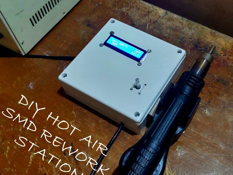
This is the second release of the Hot Air Gun station based on the Arduino microcontroller. The schematics and software parts are completely re-revisited.
In this tutorial, you can learn how to make a hot air gun controller using Arduino and other common components. In this project, the PID algorithm is used to calculate the power required and is controlled by an isolated Triac driver.
This project uses a handle compatible with 858D. It has a K-type thermocouple, a 700-watt 230 VAC heater, and a 24 VDC fan.
This controller is efficient and reliable compared to the commercial one and is easy to build.
Step 1: WiringThe schematic has been split into two parts: the main board and the high-voltage board (from another project).
The main board
The main board schematics are available in EasyEda, where you can view it and order the board if you wish.
As you can see, the cheapest op-amp is implemented in the schematics, LM358. As this amplifier is not a rail-to-rail one, the output voltage (on pin #1) can be up to 3.2 volts. If the ADC in the Arduino microcontroller is powered by 5 volts, the maximum ADC readings would be about 675, not 1023, To fix this problem the voltage regulator AMS1117-3.3 was implemented to supply a reference voltage to the AREF pin of Arduino. You can use any single power op-amp instead of LM358, but if you choose the rail-to-rail one, you can either remove the voltage regulator and supply 5v to AREF pin or adjust the R6 potentiometer carefully to avoid high voltage (over 3.3 volts) on pin #1 of op-amp.
The main board picture is shown below. As far as you can see, there are several connectors on the board that should be explained.
- JP1 is a screw-type 24-voltage power supply connector, please ensure the polarity.
- JP2 is a low-voltage part of the Hot Air Gun, reed switch, thermo sensor, and fan.
- JP3 is an interface to the AC power PCB to manage the Hot Air Gun.
- JP4 is a rotary encoder connector.
- JP5 is an I2C 1602 display connector.
- JP6 is an Arduino serial connector that allows for firmware upload.
The AC power PCB
The high-voltage pcb is also available on the EasyEda site. The schematics contain the TRIAC and opto-coipler modules allowing to isolate the board from the low-voltage part of the project.
The high-voltage board implements wide lines and should be ordered with 2oz depth to allow high current to the Hot Air Gun heater. It would be very expensive to order the complete board with 2 oz depth, so the high-voltage part was split into a separate PCB. Yet, the interface connector is completely isolated from AC power via two optocouplers OK1 and OK2. The EasyEda page contains two versions of the PCB, both are correct. You can select the one you like.
There are 4 screw-type connectors on the left side of the board and one interface connector on the right side.
- JP3 is an AC power connector, connect here the AC 220 volts from the outlet. Do not forget to install the 5A fuse before. The fuse can be placed on the rear panel of the case.
- JP6 is an optional main power switch connector. Connect the main switch here or short the pins.
- JP4 is a Hot Air Gun heater connector.
- JP7 is a connector to supply AC power to the AC-DC 24v power supply.
- JP8 is an interface connector to the main board. It supplies the isolated interface to the Hot Air Gun.
The interface connector has 5 wires that manage the AC power board:
- "+24" is +24 volts from the AC-DC power supply to activate the K1 relay. You can remove this wire if you do not install the relay
- "gnd" which is obviously the ground wire
- "E" is a power enable signal, used to activate the relay. Can be skipped.
- "P" is a Hot Air Gun heater signal, used to power the Hot Air Gun.
- "Z" is an AC zero-cross signal.
You can remove the optional 24v RTE24024 relay from TE Connnectivity if it is unavailable in your country or if you do not want to implement the safety feature in this controller. This relay completely disconnects AC power from the Hot Air Gun GX16-8 aviation plug on the front panel when the Hot Air Gun is not used. If you install an optional auto switch you can completely disconnect the Hot Air Gun from the controller and it would be safe to touch the GX16-8 connector.
To remove the RTE24024 relay completely, you should solder the relay pins as shown in the picture below by red lines. Also, if you do not want to implement the main power switch of the controller, you should solder the pins of the main power switch as shown in the picture below by the purple line.
Also, you can remove R24, VT6, and D3 from the PCB together with the relay.
Power supplyFirst of all, you need a 24v power supply for the fan inside the Hot Air Gun (several handles have a 12v fan, so you should check the one you need). As soon as the fan does not require much power I believe 1 A power supply should be enough.
As you have seen on the main board schematics there are two DC-DC converters, MP1584 based one to convert 24 volts to 5 volts and isolated DC-DC converter b0505s to reduce noise from the power source.
Or you can use an isolated DC-DC converter WSTECH or ND as shown in the picture below.
Hot Air Gun 858D handle
To turn the controller into a work station, you can order a Hakko 858D hot air gun handle as shown in the picture below. This handle is non-expensive and contains all required components: heating element, fan, temperature sensor, and reed switch.
When connecting the Hot Air Gun handle to the controller via GX16-8 plug you can use the following reference of the plug pin-out. Unfortunately, I do not know the color of the wires because my handle was assembled. I have been told that there are different kinds of Hakko 858D handles in the market and your handle can have different pinouts. To check your handle pinout you can keep in mind the following criteria:
- The plug should have two wires for the heating element, two wires for the temperature sensor, and two wires for the fan. The reed switch shares gnd with a temperature sensor.
- Earth Ground is connected to the metal body of the handle.
- The heating element has a resistance of about 60 Ohm.
- The thermocouple (temperature sensor) resistance is about 1-3 ohms.
- The reed switch should be shorted to the ground pin when the handle is near the magnet
- The fan should start working when you apply 24 volts to its terminals.
NOTE:
The wiring of the hot air gun handle may be different for different types of wands. So, refer to the wiring diagram in the photo and follow the path of the wire to find the respective pins.
Step 2: Circuit DiagramThe circuit consists of 3 parts mainly.
The Interface Part:
It consists of a 1602 LCD display with an I2C module and a rotary encoder with a push button. The display shows the set temperature, current temperature, Fan speed applied power, and current status of the handle. The encoder is used for various inputs and to navigate through the options and controls.
The Sensor Part:
It consists of a K-type thermocouple for temperature sensing and a reed switch for determining the position of the handle. The thermocouple's voltage is amplified by the op-amp to a voltage level measurable by the Arduino. The gain of the op-amp is controlled by a 200K trim pot.
The Controller Part:
There are mainly 2 controllers in this circuit. The one is a simple PWM Fan speed controller with a MOSFET. The other one is an isolated controller for the heater. It consists of a TRIAC driven by an opto-coupled DIAC and it is done by controlling the number of wave cycles that are delivered to the heater. The 4N25 optocoupler helps to maintain the sync with the AC waveform.
Step 3: The Code and LibrariesThe firmware was completely revisited in version 2. It still uses the PID algorithm to control the power to maintain the set temperature. It works by controlling the number of wave cycles delivered to the handle per second.
When the controller is turned on the wand will be in OFF state. By rotating the encoder the temperature and fan speed can be adjusted. A short press of the encoder will switch between the Fan speed and Set temperature adjustment.
The Hot air gun starts heating as soon as it is lifted up from the holder shows Ready and makes a short beep when it reaches the set temperature. It will turn off the heating as soon as it is put back into the holder. But, the fan will continue to blow until it reaches a safe temperature. After the temperature falls below 50 C it will make a short beep and displays COLD.
When the hot air gun is off, the controller will enter Setup mode if the encoder is long-pressed.
The setup mode has Calibrate, Tune, Save and Cancel, and Reset Config options.
Caution: Do not connect the controller to the power outlet when flashing the firmware. The non-isolated power supply of the fan could damage your laptop.
download the sketch source code from the project page.
Step 4: SetupThe temperature readings should be calibrated with the original value to get reasonable readings. So, to do that you should follow the following steps.
First, go to the setup mode and select the Tune option. In the tune mode, the internal temperature (0-1023) is displayed on the screen. Rotate the encoder to manually select the applied power to the hot air gun. Heat the gun to 500 degrees. Then tune the trim-pot to set the temperature to about 900 (in the internal units). Long press to the encoder return to the menu
Then, go to the setup mode and select the Calibrate option. In this calibration procedure, you must 'guess' the internal temperature readings that match the calibration temperature.
First, you should select one of the 3 calibration temperatures (200, 300, 400) and press the encoder lightly to start the calibration process. This procedure is iterative: you start with some preset temperature value in internal units the controller heats the Hot Air Gun to this preset temperature and gets ready (beeps and a question mark will be disapplied). Then you measure the real temperature with the external thermocouple. If the real temperature is not equal to the preset one, you should increase or decrease the internal preset temperature by rotating the encoder handle.
The controller keeps the temperature near the preset value all the time. To increment the preset temperature, turn the encoder right, to decrease - turn it left.
After all three reference temperature points are calibrated, long press the encoder and come to the main screen.
And now the Hot air rework station is done.
Step 5: Video!Have a look at the working of the controller in the video.
The firmware is available on GitHub.


Comments
Please log in or sign up to comment.