


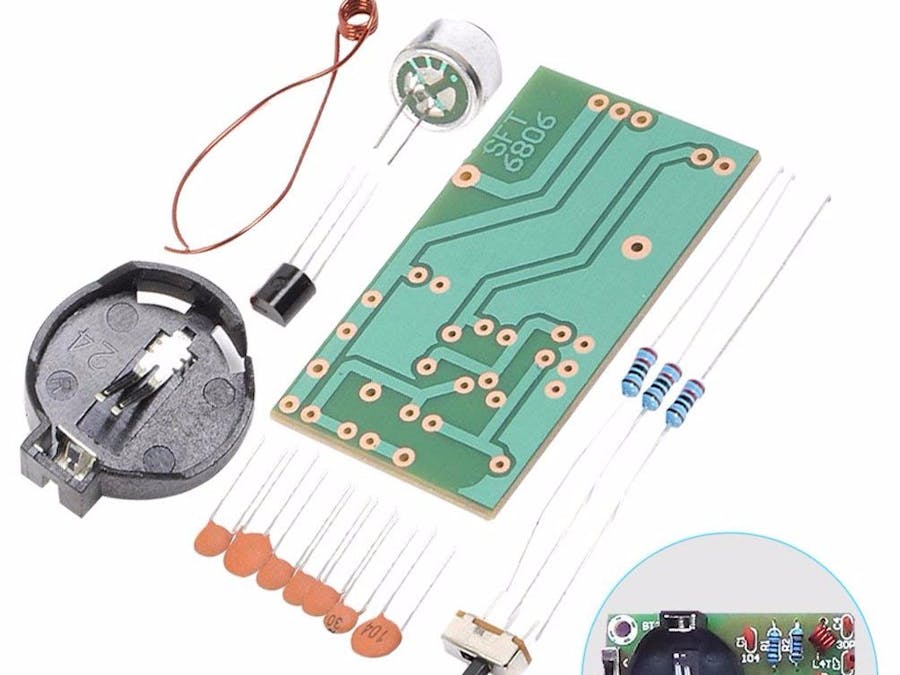
This is a simple FM microphone system transmitter kit is specially designed for radio learners. It's with the features of long transmitting distance, low power consumption, nice layout and so on. User can learn about the FM transmitting principle and also improve their soldering skills. Small kits, but much more useful.
①The MIC is an electrodes microphone, which is divided into positive and negative electrodes. The negative electrode is generally connected to the housing. Its role is to sense the weak vibrations of sound waves in the air, and output electrical signals that are the same as the laws of sound change.
②R1 is the bias resistor of the electret microphone MIC. With this resistor, the microphone can output the audio signal. This is because the MIC microphone itself has a primary field effect transistor amplifier circuit to match the impedance and increase the output capability. The microphone does not need to have too high sensitivity, otherwise it is prone to acoustic feedback and produces self-stimulating howling.
③C2 is an audio signal coupling capacitor, which transmits the acoustic electrical signal output by the microphone to the next stage.
④C3 is the base filter capacitor of transistor Q, on the one hand to filter out high-frequency noise, and on the other hand, the high-frequency potential of Q is 0. For high-frequency circuits above 50 MHz, Q is a common-base amplifier circuit. It is the foundation that can form the oscillation finally, because the foundation condition of the oscillating circuit is to must have certain gain, and then there is the feedback of the appropriate phase, it is generally positive feedback.
⑤R2 is the base bias resistor of transistor Q, which provides a small base current for Q and Q will have a larger emitter current through R3. Because of the current in R2 and R3, they will produce a voltage drop across their resistance and affect each other. As a result, they will automatically stabilize in a certain value state. This is the emitter follower.
⑥R3 is the emitter resistance of the transistor Q, acts as a stable DC operating point, and acts as a high-frequency signal load resistor with the C6, which is also part of the entire high-frequency oscillation circuit.
⑦C4 and L form a parallel resonant circuit and play the role of adjusting the oscillation frequency. Changing the capacity of C4, the diameter, pitch, number of turns of the coil L, and the thickness of the enameled wire can change the transmission frequency.
⑧C7 is a high-frequency signal output coupling capacitor. The purpose is to make high-frequency signals become radio waves into the sky. Therefore, the antenna is preferably vertically upward, and the length is preferably equal to the wavelength or integral multiple of the radio wave frequency, and the circumference should be open, and no metal objects should be blocked. Explanation: The wavelength is equal to the reciprocal of the frequency, the frequency changes, the wavelength changes accordingly, the specific length of the antenna is also related to the output impedance, the antenna thickness, etc., and then a piece of wire can be connected under the amateur condition. If you are pursuing the farthest launch distance, you can do more on your own. The kit is tested by our technicians and the launch distance can easily reach 50 meters or more.
⑨C5 is the feedback capacitor and is the key component of the circuit start-up. When analyzing the high-frequency state of the circuit, the collector of the transistor Q is the output, the emitter is the input, and the output signal is applied to the input through the C5, which generates strong positive feedback and naturally oscillates. This is the three-point capacitor oscillation circuit.
⑩C1 is the power filter capacitor, which provides a loop for the AC signal and reduces the AC resistance of the power supply.
Bebugging and installationØ After all components are soldered, the next step is to debug the oscillation frequency:
Turn on a mobile phone or radio that can receive FM radio, and then turn on the microphone power, hold the microphone while blowing or pronouncing the microphone, while on the radio Conduct a search until you hear your voice on the radio.
Ø In the whole frequency band (ie, 88-108MHz) still can not receive their own voice, then carefully use the non-induction bamboo to toggle the spacing of the oscillating coil L, only to pull or reduce the distance between each coil when toggle. Because the numerical error of the electronic components may affect the transmission frequency. If the adjustment coil is still ineffective, the L welding will be added one more time or reduced, and the above adjustment will be continued after rewelding.
Ø To increase the transmission distance, another wire is welded as an antenna at the TX. The specific length can be determined according to the effect of debugging.
Note: The oscillating coil is an insulated enameled wire. When welding, use the blade to hang off the insulating paint at both ends of the welding to weld it.

Comments
Please log in or sign up to comment.