I would introduce to you this Logic Probe, a complete instrument. It is simple but effective to measure digital logic levels 0 (zero) and 1 (one), both TTL and CMOS technology; the maximum accepted level is 10 volts but CMOS can reach up to 18 volts you would avoid. To use it just connect the Mini USB wire with black 'crocodile' clamp to the GND of your circuit and touch the probe where you want to know the logical level (in the same circuit) and look at the corresponding LED that will light up.
Usually with Arduino and similar microcontrollers as ATtiny used in this project, we find TTL at 3.3v and 5.0v where the 'zero' and 'one' logical levels are the same: from 0.0 to 0.8v is considered as 0 (LOW) and from 2.0 to 3.3 up to 5.0v is considered as 1 (HIGH); between 0.8 and 2.0 is considered UNDEFINED.
On of the three LEDs will light up at each corresponding level:
- TTL levels, both 3.3 and 5.0 volts:
low=blue <= 0.8v
high=red > 2.0v
undefined=yellow >0.8v <= 2.0v
- CMOS levels, up to 18 volts (here the limit is 10 volts):
low=blue <= 1.5v
high=red > 3.5v
undefined=yellow >1.5v <= 3.5v
- MCU ATtiny 1614 SMD
- Mini USB female PCB SMD connector
- 2 x SMD capacitors 100nF
- SMD Resistor 270 Ohm
- SMD red LED
- SMD 662k voltage regulator to 3.3v
- 16 x strip line thin pins 0.6mm diameter
- Double faced SMD PCB
- Sliding switch on/off
- 6 x 10k Ohm 1/4W Resistors 1%
- 5k6 Ohm 1/4W Resistor
- 22 Ohm 1/4W Resistor
- 5k Ohm 1/4W Resistor 1%
- 3 x 150 Ohm Resistor
- 15 Ohm 1W Resistor
- BC337 NPN Transistor
- Axicom SMD 3.0v Relay
- 1N4148 Diod
- Ceramic Capacitor 100nF
- Push Button normally open
- Red LED 5mm
- Blue LED 5mm
- Yellow LED 5mm
- 300mA/h 3.7v 1s Lipo Battery
- Small Plastic box (see 3D project below)
- Metal Probe
- around 20 copper 0.6 small rivets (for pass through holes)
- Double faced PCB
- 3 x strip line pins for the Switch
- 2 x strip line 90° pins for the Battery
- 2 x Screws 3mm and supports
- 'Crocodile' black Clamp, 40cm of black wire and a Mini USB male connector
Inspired from John Bradnam's ATtiny 1614 Project I bought a couple of this microcontrollers to take a new way and enjoy a new adventure, I made MyTiny first testing circuit. Everything is working on my choice to power it at 3.3v. Up to today I tested and verified: digitalRead, digitalWrite, analogRead, analogWrite both PWM and DAC; I provided a serial monitor though pins RX/TX <-> FTDI serial interface and SoftwareSerial library; finally I connected an OLED 128x32 display by the way of SDA/SCL and Wire library. Cool!
To program the ATtiny by the way of anArduino NANO and IDE please read Bradnam's instructions at above link.
Additionally, in this circuit I decided to include a complete circuitry + code to recharge the LiPo battery. For this reason the USB power input of 5.0v is controlled by a 15 Ohm 1W resistor and a relay, to limit the charging current and cut it off when 4.2v of battery charging limit is reached. When the battery is discharged, at 3.2v, considering the sole circuit using 50mA, the battery will receive the remaining 70mA of charging current [(5.0-3.2)/15=120mA]; close to the end of charging, at 4.2v, the battery will receive only a few mA of charging current [(5.0-4.2)/15=53mA]; after that the relay will disconnect the USB power and battery will receive nothing and will start to slowly discharge as per normal operation. To the Mini USB connector you can connect alternatively the black 'crocodile' clamp wire in order to measure levels (to GND), or an USB cable to recharge the battery (i.e. to computer).
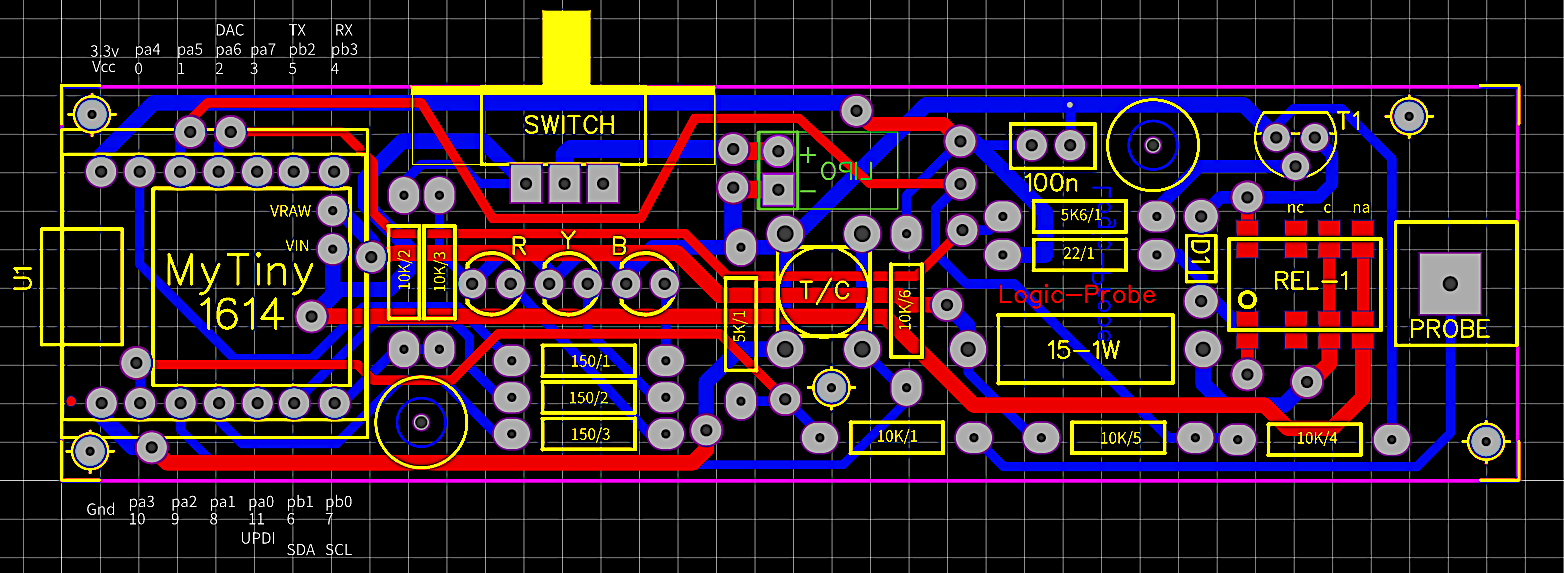
The 5.6k/1 and 22/1 resistors, D1 and T1, all are to control REL-1 on/off; 10k/5 and 10k/4 is a voltage divider "by two" to measure USB power voltage; 10k/1 and 5k/1 is a voltage divider "by three" to measure probe voltage; 10k/2 and 10k/3 is a voltage divider "by two" to measure battery voltage; 10k/6 is to pull-up the T/C push button; three 150 Ohm resistors and three coloured LEDs complete the main circuit. Please try to select the couples of resistors as voltage dividers as similar values as possibile at 1% of precision to have correct analogRead() readings. In case of differences you may correct the readings making arbitrary corrections +- in percentage where the code calculates the voltages: 'VRaw=(n1 + ((n1 * 0.0) /100));' and 'VBatt=(n1 + ((n1 * 0.0) /100));' (now values are 0.0 due to no corrections).
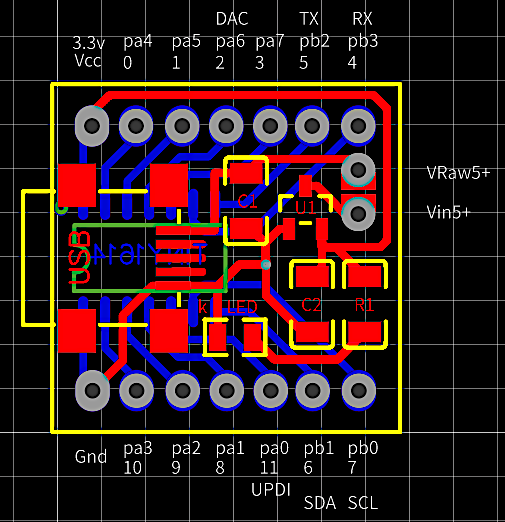
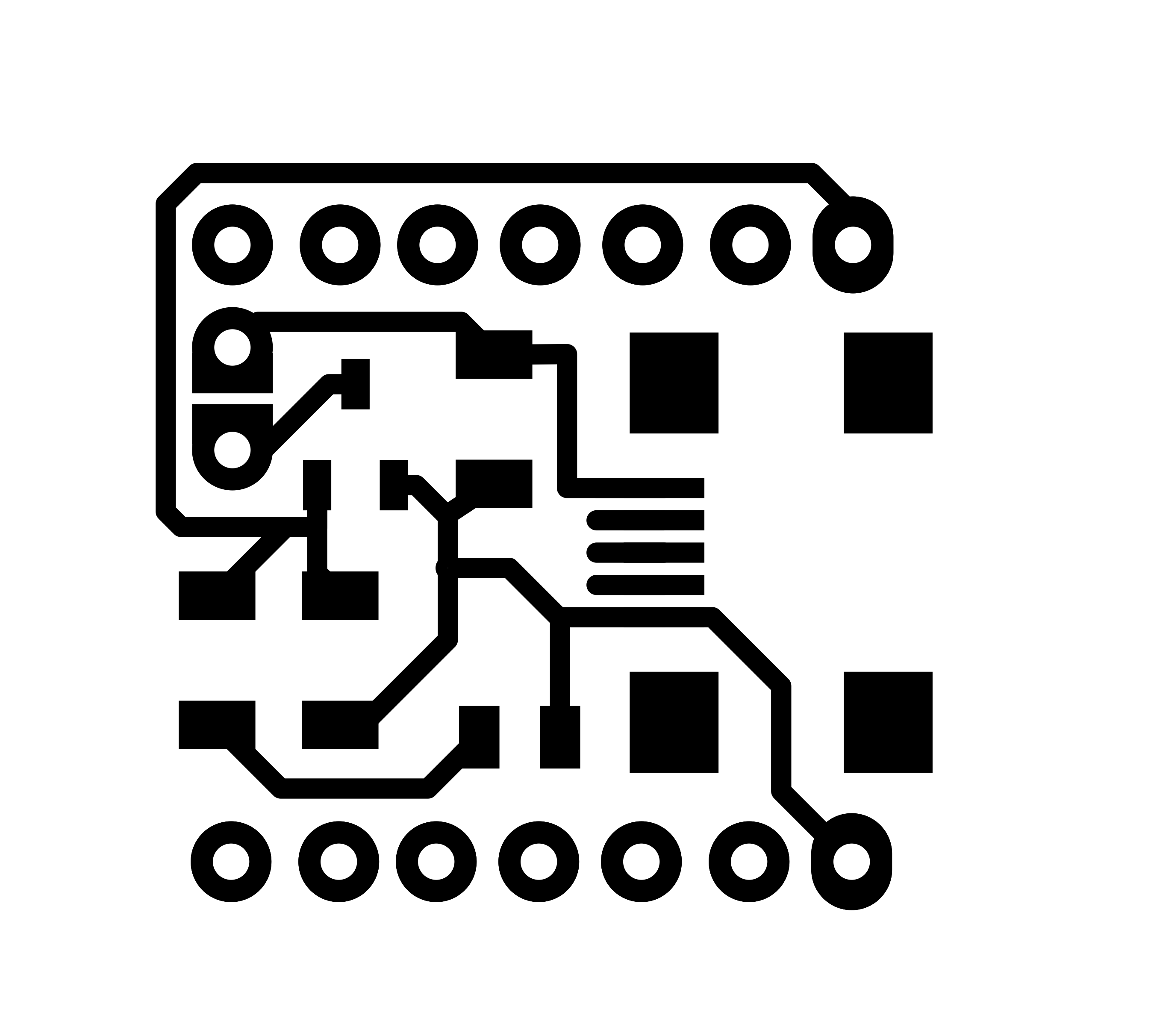
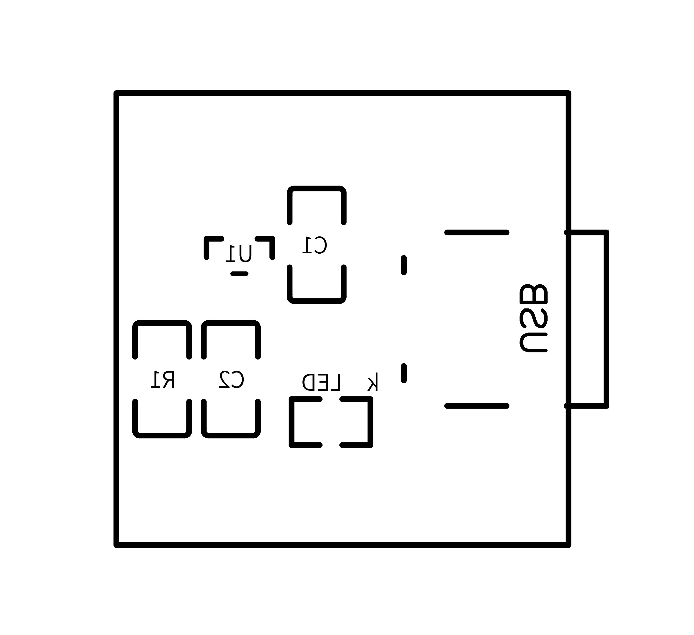
The MCU small board is a double faced PCB with SMD components: the ATtiny microcontroller, a mini USB, two capacitors, one resistor for the LED, and finally the voltage regulator to 3.3v.
A Few Pictures!If you like to see datas on serial monitor for debugging or other purposes you have to uncomment the library "#include <SoftwareSerial.h>" and set "const boolean IsDEBUG = true;"; additionally you have to connect a Serial-to-USB converter as FTDI (rx) to microcontroller (tx) port, together with a software serial communication like CoolTerm set at 9600 baud.
Charging values:
If you change the battery with different power (A/h) you have to modify the software parameter accordingly (CBatt). Also changing the 1W resistor for a faster or slower charge i.e. from 15 to 12 or 18 Ohm, please remember to change also the parameter (VResis). I liked to do some calculation during charging or during normal probing operation, here there are:
- CBatt = 0.3 (battery power in A/h)
- VResis = 15.5 (resistor value in series between PowerSource and Battery, please measure the exact resistor value and put it there;
- ICirc = 0.05 (estimated maximum current consumption of the circuit without battery charging);
- VPower = 5.0 (charging PowerSource voltage from USB) not a constant, it will change in readings;
- VMinPower = 4.6 (minimum voltage from USB to charge battery);
- VBmin = 3.2 (absolute minimum voltage);
- VBWmin = 3.4 (working minimum voltage);
- VMax = 4.2 (absolute maximum voltage);
- VBchgd = 4.0 (battery voltage, or more, to consider it already charged at power-on);
- ETFact = 1.5 (estimated time of charging factor);
- OvTiFact = 1.2 (overtime of charging factor, in addition to ETFact);
- VInitBatt = initial battery voltage, after power-on or just after charged or at start of charging;
- VBatt = actual battery voltage;
- IBatt = (( VPower - VBatt ) / VResis) - ICirc (charging current; 0.066A at 0%, 0.034A at 50%, 0.002A at 100%);
- IBattAvg = (( VPower - ((VMax+VBmin)/2) ) / VResis) - ICirc = 0.034A (average charging current);
- SoC = 100 - (( VMax - VBatt ) * 100) (state of charge in %);
- TFull = ( CBatt / IBattAvg ) * 60 = 529 minutes (time of charging at average current and battery at VBmin);
- TMaxChg = TFull * ( VMax - VInitBatt ) * ETFact * OvTiFact (estimated maximum time of charging considering initial voltage state, in minutes);
- TChg = ( TFull * (VMax - VBatt)) * ETFact (restimated remaining time of charging in minutes);
- ChTimeStart = time elapsed as minutes from power-up;
- ChTimeEnd = time end of charging as minutes from power-up;
- ChTimeNow = time as minutes from power-up;
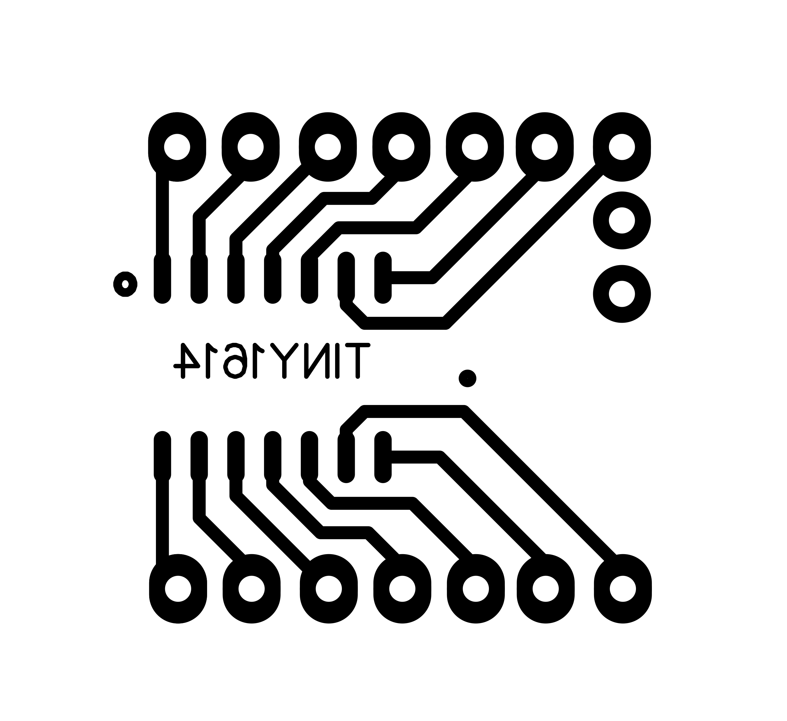
I used two double faced PCBs for that reason in the main board approx. 20 pass through rivets or pins are used to solve routes for whole circuit. There are also 5 alignment spots holes to make first. I designed on every PCB face these 5 alignment spots. In download section you have all PCB files, components and solder faces, mirrored, for downloading and printing by the way of a laser printer on "yellow" or "blue" sheets; I used the blue ones but also the yellow ones are good and the price is lower. I have to say the blue sheets are better... When printing remember to disable toner saving settings, use instead 1200 dpi resolution to have deep real black result. The toner transfer process from magic sheets to PCB is made by the use of an hot iron... Around in the Net there are some tutorials showing how to produce a good PCB but remember these important points: clean perfectly and slightly brush the copper with a kitchen ruvid sponge, 5 minutes of ironing (do not press much), cold water thermal shock, two faces alignment by the way of 5 holes (I used 5 pins on a large white LED surface to see holes), protect with transparent adhesiv tape the other face during corrosion process. Printing also components designs makes the project "professional" and more simple to place them correctly :-)
The small PCB for the microcontroller mounts SMD components. There are just a few components, I soldered them using a small soldering iron and some soldering paste: "Solder paste is a combination of a powder made up of metal solder particles and sticky flux that has the consistency of putty. The flux not only does its usual job of cleaning the soldering surfaces of impurities and oxidation, but it also provides a temporary adhesive that holds the surface mount components in place". Place a very small amount of soldering paste on copper spots, place a component one a time, hold it there and finish the work with the soldering iron, then pass to the next component and so on till the end.
To join this small board with the main one I suggest to use thin strip line pins with diameter of 0.6mm.
Three LEDs status:Normal Operation (no USB power):
- blue = logic 0
- yellow = logic 'UNDEFINED'
- quick blinking yellow = low battery warning (please recharge)
- red = logic 1
Charging Operation (with USB power)
- blinking red = charge status 0 - 20%
- blinking yellow and red = charge status 20 - 40%
- blinking yellow = charge status 40 - 60%
- blinking blue and yellow = charge status 60 - 80%
- blinking blue = charge status 80 - 90%
- slow blinking blue = charge status 90 - 100%
- quick blinking blue = already charged
- quick blinking yellow = charging overtime warning (please disconnect USB)
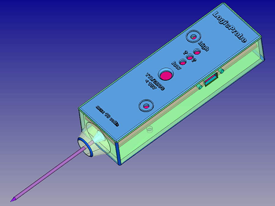
- 25.03.2021: to complete the project I prepared two 3D .STL models at this link: https://grabcad.com/library/logic-probe-1 where you may download files regarding a shaped box and his cover panel for the Logic Probe to print by the way of a 3D printer.
Happy Probing!







Comments
Please log in or sign up to comment.