I wanted it! I have been invidious of my friend Taggi's big car showing on windscreen the speed. I had to have it, I had to make it by myself of course!
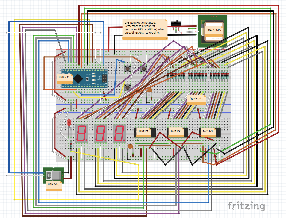
Projecting the circuit the most difficult and confusing part have been the connection of the 7 segments displays to the BCD decoders because numbers are "inverted" (mirrored).
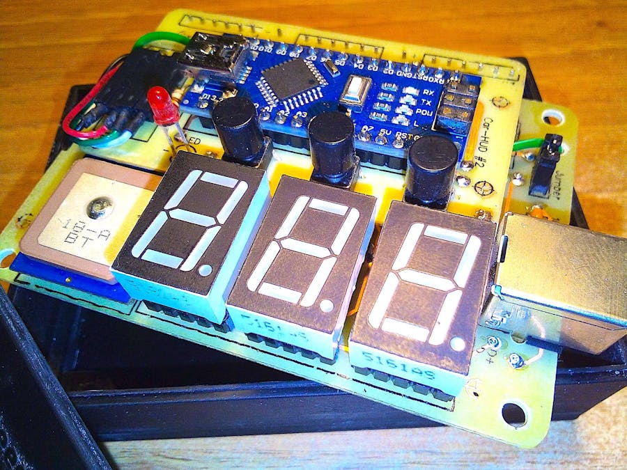
There are 3 buttons: + and - for increasing/decreasing brightness and S/H to switch between Speed in km/h and Heading in degrees; in case of Heading also the red LED is on, it means "degrees" of compass (1-360°) when moving. It isn't an electronic compass, it is a GPS and you need to move to have the right information of the direction you are moving to. The brightness is saved in EEPROM memory after a minute. Brightness is changed both on displays and on LED by the way of PWM pins.
An important part of the code is for collecting datas from GPS, mainly speed and direction, taking them out from every NMEA sentence. Even using String class, mostly for Serial NMEA sentences manipulation, the whole elaboration flow is stable and solid; it uses "serialEvent()" to receive data from GPS one time per second, than calls "nmeaExtractData()" and finally it checks data packet with "nmea0183_checksum() to be sure of data integrity. If you use another make and model GPS be sure the sentences have the same structure or you have to make some changes here. For example EM406A uses "$GPRMC" packet id, BT220 uses "$GNRMC" instead... just a small name change... A useful link can help you with checksum test: https://nmeachecksum.eqth.net - Here an example of a complete NMEA sentence, it contains: id, time, validity, latitude, longitude, speed, true course, date, variation and checksum.
$GNRMC, 095836.000, A, 4551.9676, N, 01328.7118, E, 2.09, 341.84, 280519,, *08
The sketch provides to enable the latch for every single display BCD decoder one at a time, set the code number on the binary 4 bits bus, disable the latch, and so on when value changes. Left side not significant zeros are blanked (not displayed).
Before loading a new sketch to the MCU remember to take out the Jumper: it is connected to Rx pin of Arduino and during loading it is for sure in conflict with GPS Tx. After software loading put again in place the Jumper to restore normal functionality.
- 1 x MCU Arduino Nano
- 3 x 5161as seven segments displays, common cathode, red
- 1 x Beitian BN-220 serial TTL GPS (1 Hz GNRMC sentences)
- 1 x Jumper
- 3 x buttons (normally open) + 3 x caps
- 22 x 1/4W 220 ohm resistors
- 1 x 3mm LED, red
- 2 x 100n capacitors
- 3 x 14511 BCD decoders + latch
- 1 x USB "B" female
- 1 x strip line 2x male pins (for Jumper)
- 1 x strip line 4x male pins to bend to 90° (for GPS)
- 1 x pigtail cable connecting GPS to 4 pins onboard
- 22 x strip line male pins to join two PCB in a stack
- 1 x piece of double sided adhesive to stick GPS on PCB
- 6 x turned strip line 5x female pins (for displays)
- 50 x copper 0.6mm rivets
- 8 x M3 screws
- 4 x M3 female towers 20mm high
- 1 x plastic box + cover (look at my 3D files ready for printing, below)
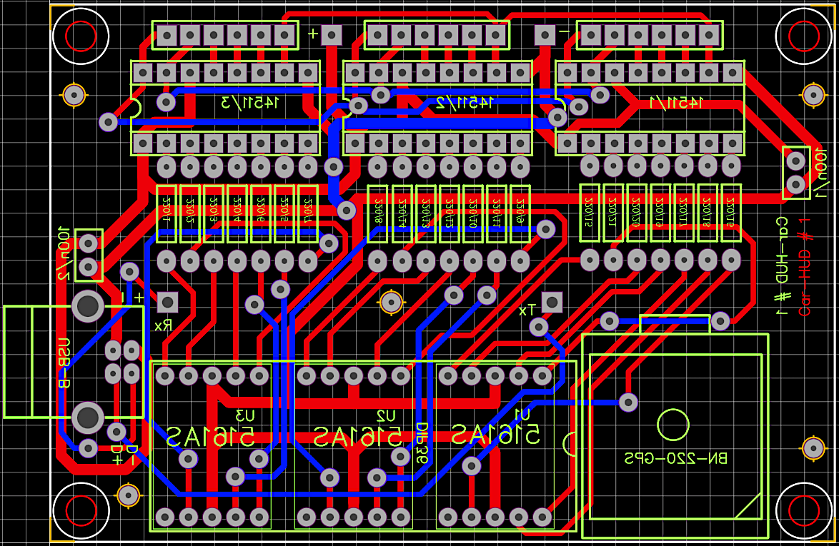
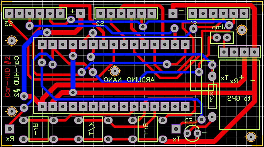
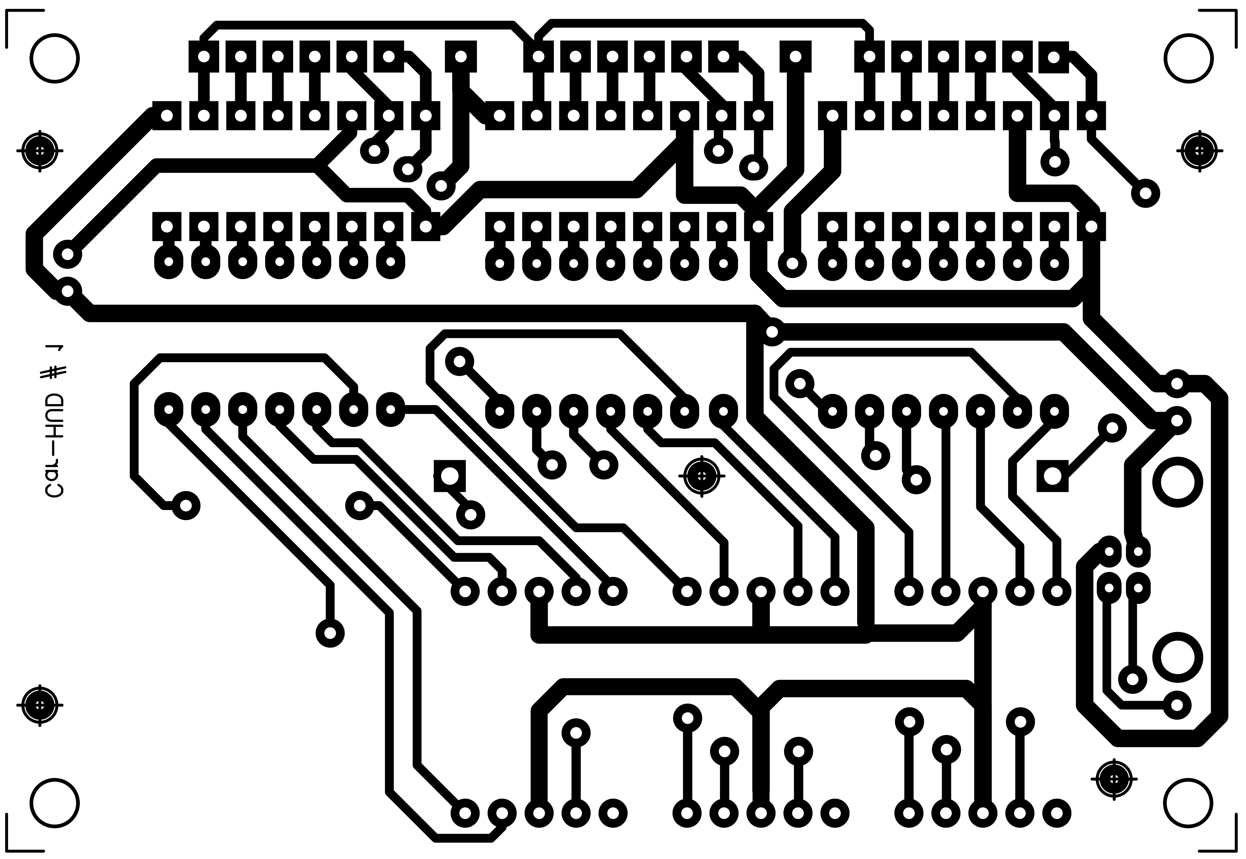
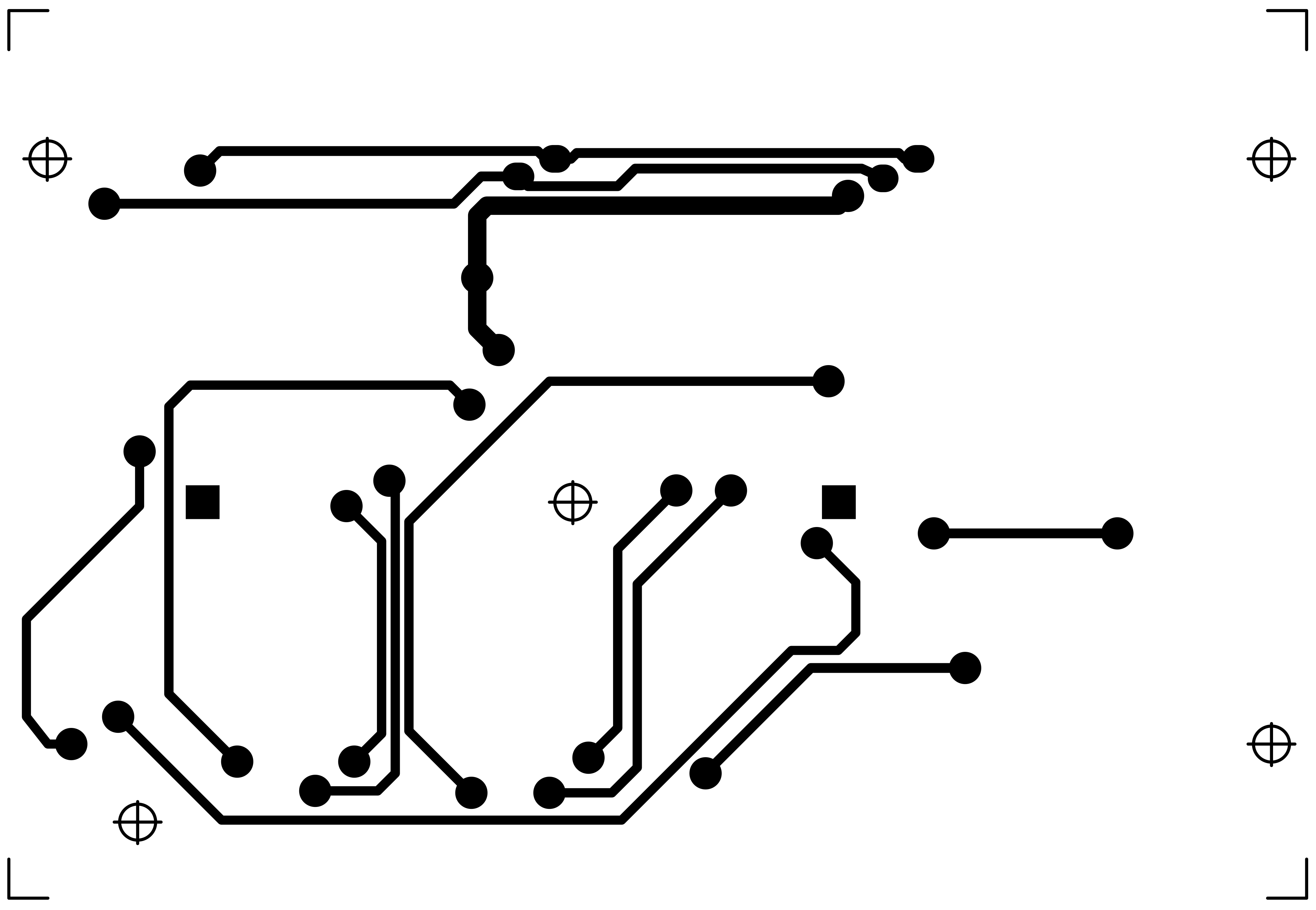
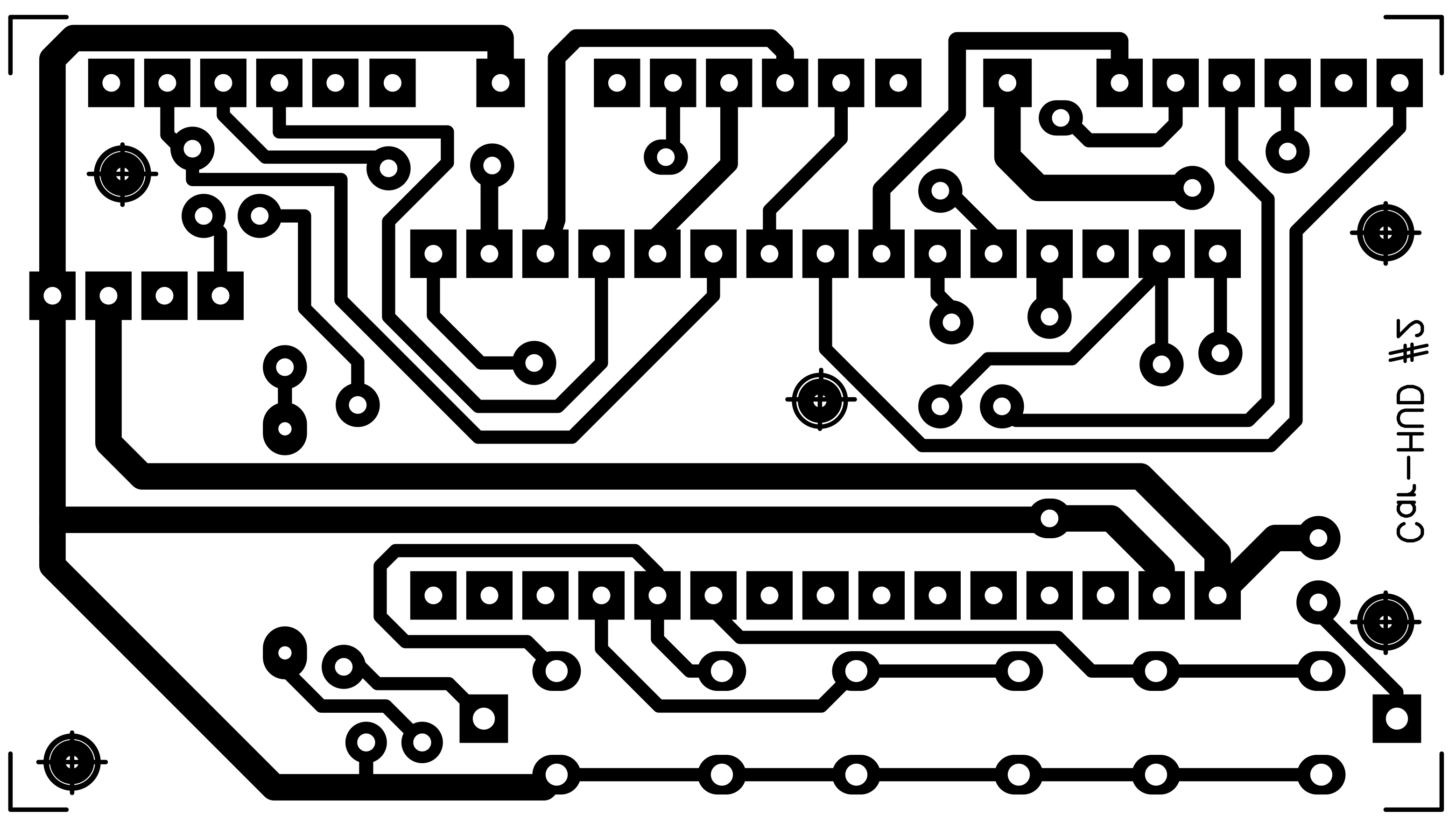
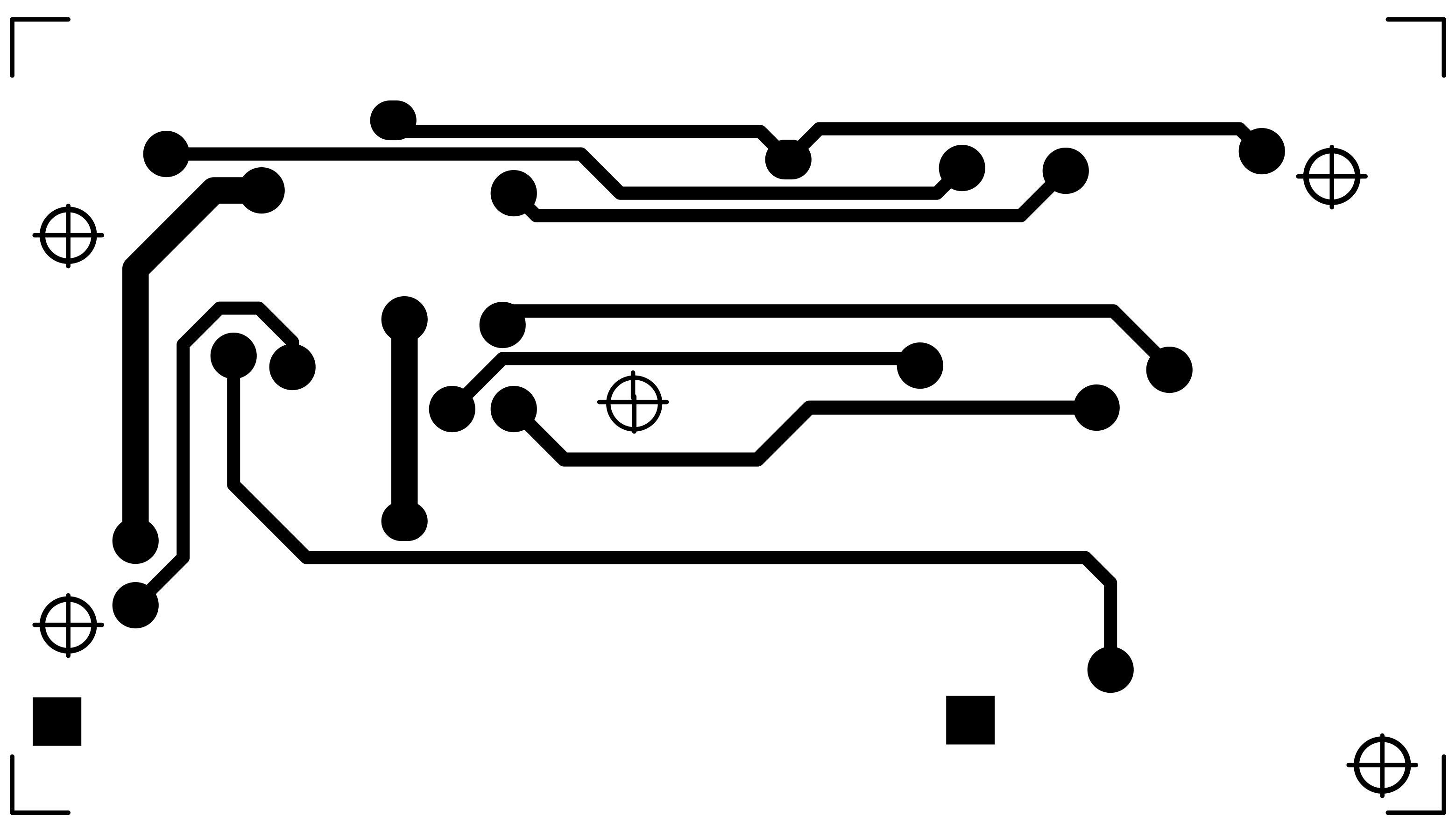
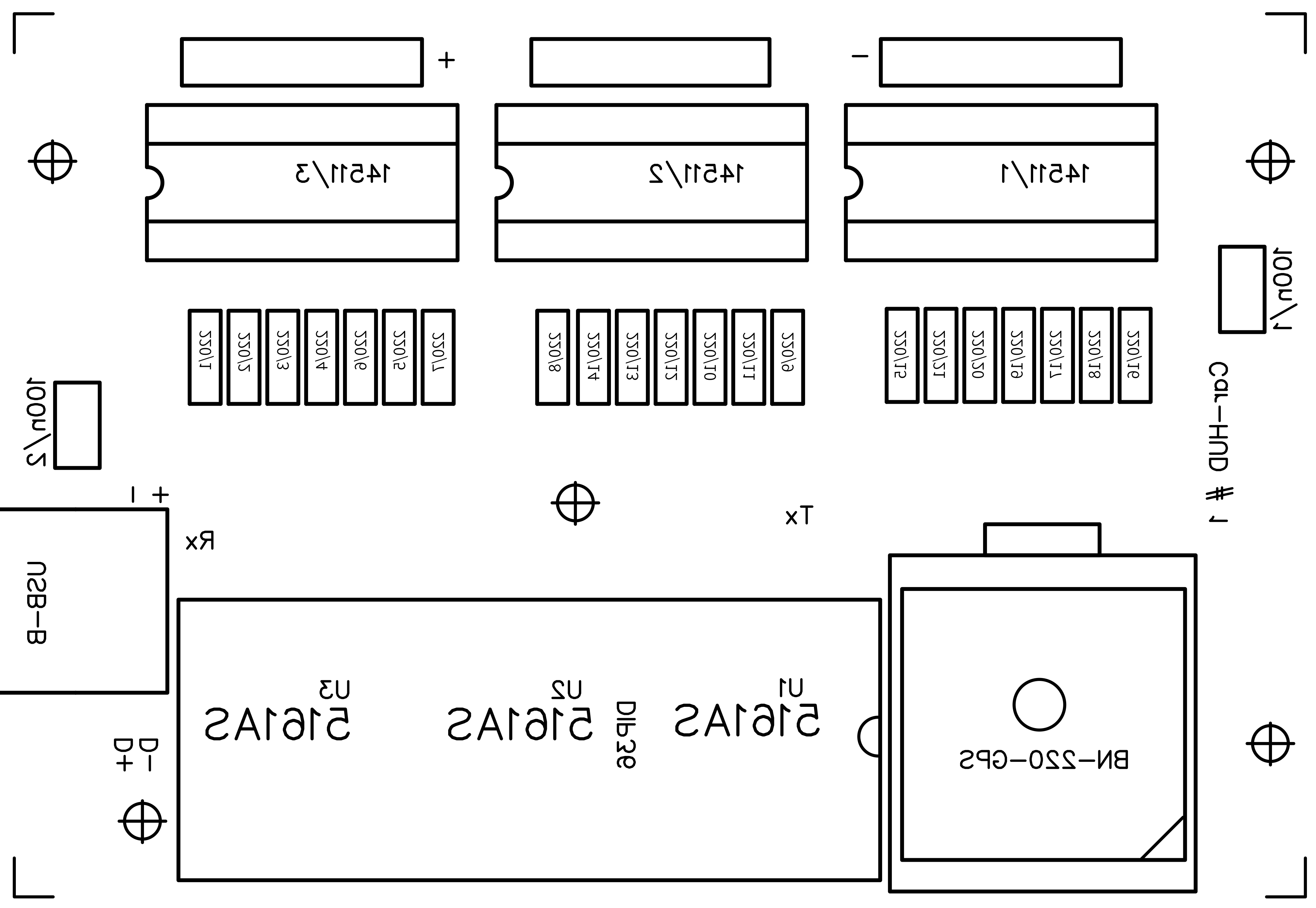
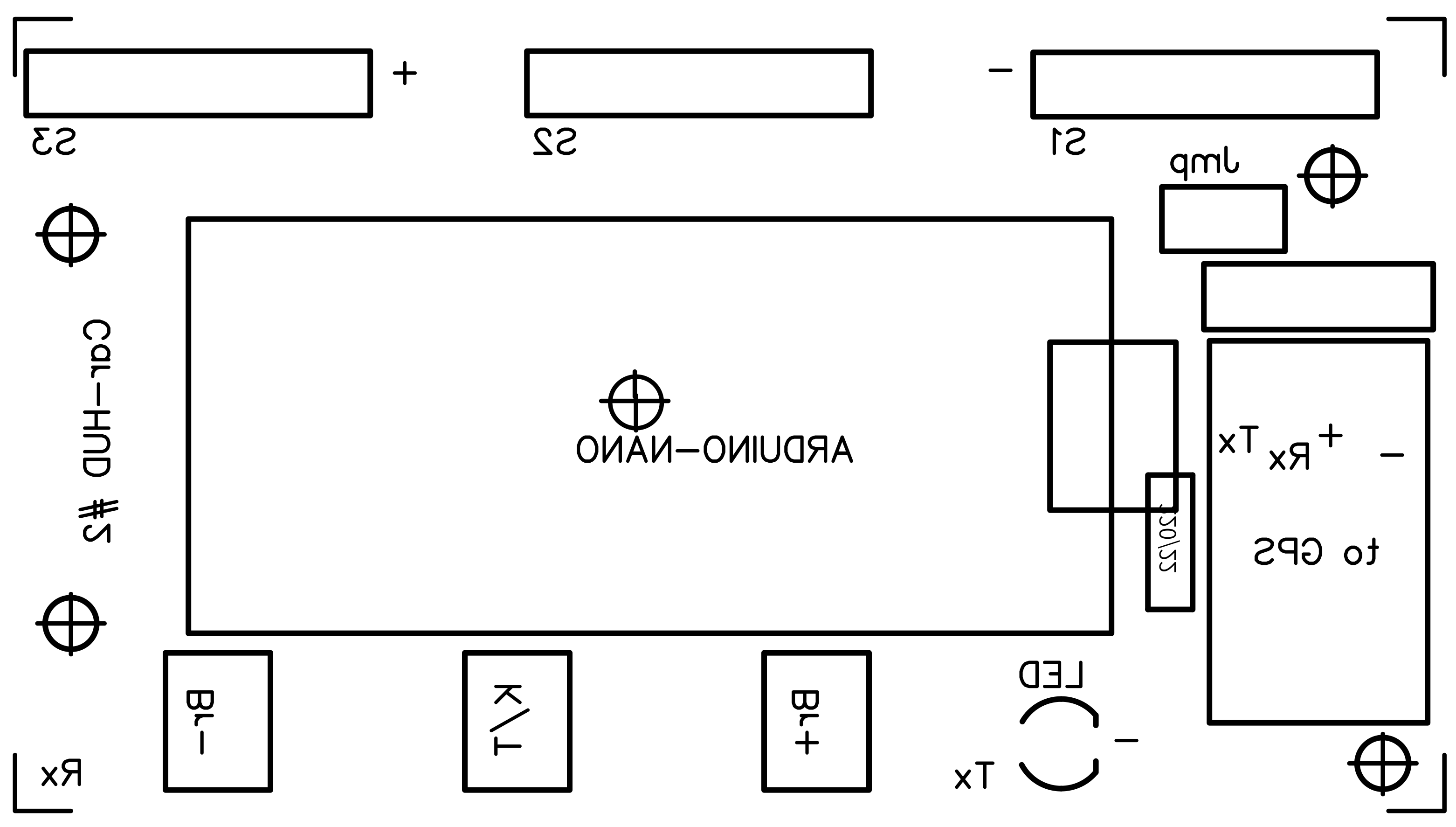
I used two double faced PCBs for that reason around 50 pass through rivets or pins are used to solve routes for whole circuits. There are also 5 alignment holes to make first. I designed on every PCB these 5 alignment spots. In download section you have all PCB files, components and solder faces, mirrored, for downloading and printing by the way of a laser printer on "yellow" or "blue" sheets; this time I used the blue ones but also the yellow ones are good and the price is lower. I have to say the blue sheets are better... When printing remember to disable toner saving settings, use instead 1200 dpi resolution to have deep real black result. The toner transfer process from magic sheets to PCB is made by the use of an hot iron... Around in the Net there are some tutorials showing how to produce a good PCB but remember these important points: clean perfectly and slightly brush the copper with a kitchen ruvid sponge, 5 minutes of ironing, water thermal shock, two faces alignment by the way of 5 holes (I used 5 pins on a large white LED surface to see holes), protect the other face during corrosion process. Printing also components face makes the project "professional" :-)
NOTES: the pictures are taken before the very last version, it means a few details can be different: i.e. the strange green wire around the PCBs in the final version disappears, or the Jumper has moved from PCB #1 to PCB #2. You should setup the GPS at 9600 bps speed, 1Hz GNRMC NMEA sentence only; this can be made using its own setup software. Finally, before solder the USB female connector, stick a small piece of insulating tape under it to avoid unwanted contact with a copper line, on the component side, just below it.
Giving power for the first time you will discover the numbers are "unreadable", because it is made to look at them reflected on the windscreen (mirror). Install it in the car in the front of driver's seat, find a comfortable place and fix it. I suggest to connect the USB power cable after the ignition position so it will switch on / off when engine on / off. That's all ladies and gentlemen!
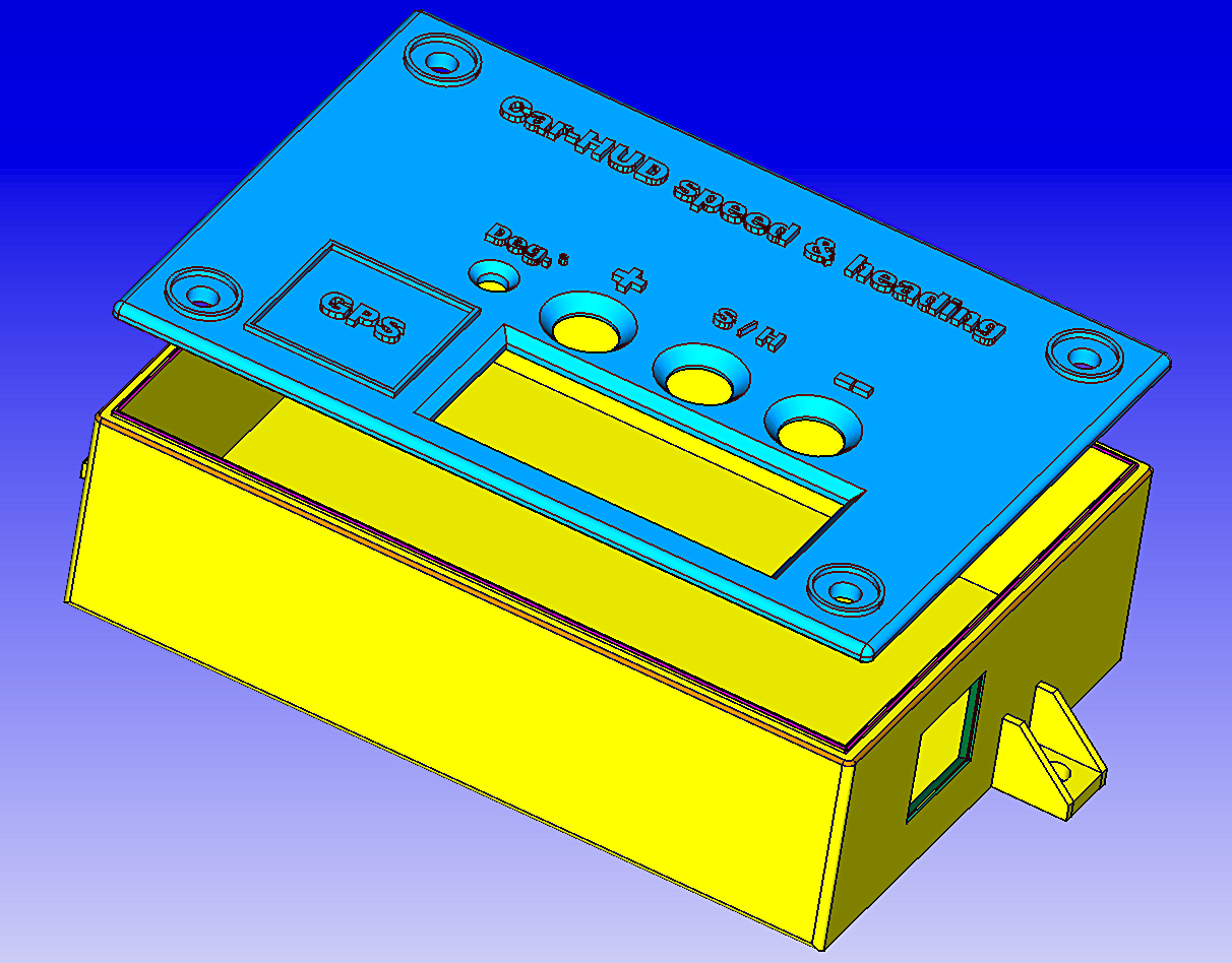
News and Improvements:- 25.03.2021: to complete the project I prepared two 3D .STL models at this link: https://grabcad.com/library/car-hud-1 where you may download files regarding a shaped box and his cover panel for this project to print by the way of a 3D printer.
- 20.07.2021: it is available a V2 (version two) of the software that together with two wires and one resistor you will have altitude information on the display as thousand of meters (i.e. 0.89 = 890m), just press another time the S/H button! Instructions: 1) setup GPS to output also $GNGGA nmea sentence by the way of its own software; 2) cut actual connection between d5 Arduino pwm pin and the rest of the circuit, connect it to central display decimal dot pin with a 220ohm resistor; 3) connect d13 Arduino digital pin to the circuit where d5 was connected; look at few pictures here below; 4) install V2 sketch on your Arduino Nano.
- 01.11.2021: version V2.2 is ready for you. What new? About altitude (already present with V2) the hud shows full value up to 999m, starting from 1000m it shows values in thousand, i.e. 1.24 (1240m) or 2.02 (2020m). I added a LDR photoresistor GL5539, a 10kOhm resistor and 2 wires. Look at the pictures below for V2.2 mods and install V2.2 sketch on your Arduino. The LDR sensor will modify brightness automatically (3 levels) depending of the light level (day, cloudy or night). Buttons (+) and (-) are still working to manually modify brightness, they have priority; to return back to automatic just press together (+) and (-) buttons for a while. The internal EEPROM to store brightness level is not used anymore. Let do V2 mods first!
- 16.04.2023 some USB power cables have rx/tx wires connected to the ground. This does not allow GPS to communicate with MPU. Be sure to have the USB power cable with just + and - wires...
When driving, just drive. Drive safe!





Comments
Please log in or sign up to comment.