


Hardware components | ||||||
_PnKPri8a6q.jpg?auto=compress%2Cformat&w=48&h=48&fit=fill&bg=ffffff) |
| × | 1 | |||
I love playing music by the way of an electronic drum set. My personal one is an 8 elements XDrum DD550(D), 3 cymbals and 5 pads; its central unit has a MIDI output I use to connect computer and Ableton Lite software where I decide what sound every element has to play: it is a perfect combination! But what about adding some more elements like a cowbell, a tom, a cymbal or even a pedal?
With Z-MIDI6dp, this is the name I have given to the equipment I am going to introduce here, you can add 6 more elements to your music set. Any combination of pads/cymbals and pedals is allowed. In every rear panel 6.3mm input you could connect:
- a single sensor pad (mono plug)
- a single sensor cymbal (mono plug)
- a switch pedal like "sustain" one (mono plug)
- a variable level pedal like "expression" one (stereo plug)
- a double sensor pad/cymbal (stereo plug with split to 2 x mono plugs)
In case you have a double sensor pad/cymbal with a stereo 6.3mm plug, i.e. a snare + rim, DO NOT connect it directly to Z-MIDI6dp but use a split cable with 2 mono plugs. This because stereo plugs are allowed here only for "expression" type pedals; this kind of pedal needs 5 volts power to work provided by the ring part of the connector, the double sensors pads/cymbals don't. Additionally, in all connectors the ground is connected to GND, the tip provides the input signal of the single element.
On the rear panel you have the six 6.3mm inputs and an USB-B strong connector to connect your computer and Ableton Lite software. I use a Macbook, and Arduino MIDI equipment Z-MIDI6dp is recognised without drivers or anything. I am sure also Windows will do a good job. For some tests I tried also GarageBand software, I think any software using MIDI input and MIDI control will work.
On front panel there are six LEDs to show the six inputs activity, an OLED display very useful to show settings, a classic MIDI OUT connector and a rotary encoder with push button. Push knob button to enter Setup mode and follow on display instructions to change parameters as Input Type, Channel, Music Notes, Sensitivity and others, if needed.
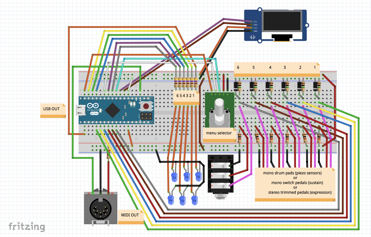
3D Project Pictures:As MCU I used an Arduino Micro and you should use the same because the USB is recognised straight forward as an USB device when connected to a computer software like Ableton Lite; if you decide to change it with another Arduino flower be sure it does the same job. In the front panel is provided also a classic MIDI OUT connection where the serial TX shares a 31250 baud rate data transmission; you do not need to use MIDI port if you already use USB communication. Anyway you have to connect the USB somewhere at least to power the device because MIDI port doesn't provide power.
As mentioned above, the six inputs accept a switch (mono jack pedal), a potentiometer (stereo jack pedal) or a piezoelectric sensor (mono jack drum/cymbal) in any combination. Six resistors (1k ohm) are connected to the ring of the jacks providing 5V reference only for potentiometer ones; for the others they will be connected to the ground, it is correct, they have nothing to do in this cases. Six resistors (1M ohm) and the six zener diods (5.1V) are connected to the tip of the jacks providing to limiting the spikes from piezo sensors, but they are intended to do "nothing" in case of switches or pots. One more time: do not connect double sensors pad/cymbals directly to the input but put in the middle a split cable with stereo to double mono jacks (see the picture below).
There are six LEDs with their resistors (470 ohm) to show activity of the six jack inputs. A beautiful 128x64 pixels OLED display, by the way of a i2c bus connection, will show you settings and parameters you may change if needed: the rotary + push button knob is used for these purposes.
To understand MIDI serial communications protocol I recommend to have a look at the following link, it is very interesting: (https://en.wikipedia.org/wiki/MIDI). Briefly, when you hit a drum pad, you press a music keyboard key, you turn a volume knob or you close a pedal switch, etc., these mechanical actions are translated into digital messages with specific and recognisable sentences as ID + Information (id, channel, action, pitch and velocity); messages are transmitted by the way of a serial communication, USB or MIDI port, to a computer software and, finally, translated into music or actions. The same pitch (music note) can be played as a piano note, a drum cymbal, a flute note as you decide, as well as an "expression" pedal can modify volume, balance, reverbe, bass/mid/high tone or many other things; these are just some examples. Read your software user manual (i.e. Ableton Live or GarageBand) to understand how to link MIDI sentences to music or actions. In the case of Ableton Live you have to enable the Arduino Micro MIDI Port both as Track=ON to play notes, and Remote=ON to control it.
In the Loop() the main job is done by checking the inputs of the six ports as well as whether you are pressing the menu knob or not. To enter configuration mode you have to keep pressed the knob for around 4 seconds... Inside the configuration, you have to set the 6 ports according what kind of device you have connected to every input port, pad/cymbal or pedal; you could modify also some other parameters as channel, min/max values, reverse, pitch/note number, length of the drum wave, antibouncing, control command, etc. and everything will be written in the Arduino EEPROM memory. I suggest to accept default values at the beginning and to modify them carefully one at a time and test it before change another one especially DrumLen, MinValue, MaxValue and Antibouncing.
PARAMETERS:
- InputType: 1=piezo/drum 2=switch/pedal 3=trimmer/pedal (here you specify what kind of device you are going to connect on the Input Port 1-6)
- Reverse: 0=no 1=yes (some pedals are on/off others are off/on, others are high/low or low/high; reversing it will change the sequence of function)
- Channel: 1-16 (usually keep it as CH 1 but you may change MIDI channel here)
- NotePitch: 0-127 (octave and note combination, i.e. 2 C#) (for a drum this parameter change the Octave and the Note when you hit it)
- DrumLen: 5-95 m/sec (default value is 50 m/sec, try more in case of popping (2 sounds with 1 hit), or try less if you are very quick and lose sounds of some hits; with 50 you should play 1/64th of beat at 60bpm, and 1/32th at 120bpm... very quick!
- MinValue: 0-63 (minimum value you expect from the device, default is 0 for pedals and 30 for drums; for drums is the threshold: i.e. 25 more sensitive, 35 is less)
- MaxValue: 64-127 (maximum value you expect from the device, default is 90 for pedals and 100 for drums)
- Antibouncing: 0-63 (default value is 60 for a switch/pedal, 2 for a trimmer/pedal, 0 for a drum)
- ControlNumber: 0-119 (for a pedal this parameter change the functionality of the device on the computer software as CC ControlChange i.e. 1=modulation, 7=volume, 64=sustain, etc. and many others also for free use too i.e. those between 102-119)
It is provided a live monitor where you could see on display (look at the picture below) what is received from the input device and what is transmitted to the computer: P=port (1-6), T=type (P=pad T=trimmer S=switch), CH=channel, RAW=received value, VAL=sent value and NT/CC= note/octave or control change number. It is useful to understand what is happening when you hit a drum or press a pedal.
Uploading newcode to the Arduino Micro occasionally does not work? It happened to me just one time a few days ago. No panic, here it is the solution: "Press and hold the reset button on the Micro, then hit the upload button in the Arduino software. Only release the reset button after you see the message 'Uploading...' appear in the software's status bar. When you do so, the bootloader will start, creating a new virtual (CDC) serial port on the computer. The software will see that port appear and perform the upload using it. Again, this is only necessary if the normal upload process (i.e. just pressing the uploading button) doesn't work".
Thanks to: https://www.arduino.cc/en/Guide/ArduinoLeonardoMicro
Parameters say how to manage the single input port and according to them called the correct function: readDrum(), readSwitch() or readTrimmer(). The functions provide to translate analog input to digital output; at the end of every function the information is sent to USB and MIDI Serial1 ports and MidiUSB.flush() is called. Values are reduced from 10 bits (0-1023 value) to 7 bits (0-127 value) according to the protocol: "Map" instruction do exactly this, scaling values to a lower range; Map is also used to expand a value from an even lower range, i.e. the one from a drum, between Min and Max, expected values between 30 and 100, to a better, finally, 0-127. "Reverse" parameter works together with "Map" capsizing the range if requested (0-127 to 127-0 or viceversa). Before sending the Note or the Control MIDI message to the USB and to the MIDI port the value is checked by "Antibouncing": the new value, compared to the previous one, must be greater than the sum of previous + antibouncing values otherwise will be ignored. For a Trimmer Pedal is good to set Antibouncing around 3, in this way self small changes of the value, in this example 1 or 2, will be ignored avoiding to saturate the transmission line with unnecessary and unwanted MIDI messages bouncing between two values like 24-25, 25-24, 24-25, 25-24... Of course the granularity (resolution) of the Trimmer Pedal is lower with high Antibouncing set. The default value is 2.
All 9 parameters for every 6 input ports compose a 9x6 matrix for a total of 54 bytes, read from EEPROM memory at the beginning of the sketch, and updated on exit of Menu Setup, so all parameters will stay in memory after Z-MIDI6dp power off. Default 6 input types are: 1-4 pads, 5=switch pedal and 6=trimmer pedal. They say it is a limit of 100000 writes on every single byte of the EEPROM, so Update instruction writes in memory only if necessary, only if the byte is different, to save its life.
The sketch code contains remarks about Octave/Note/Pitch, default parameters and other things I hope will help you to understand better what I did and what code does.
- Nr. 1 Arduino Micro + DIP 36
- Nr. 1 OLED i2c 128x64 pixels display
- Nr. 6 female audio rear panel connectors 6.3mm
- Nr. 6 LED + front panel holders
- Nr. 6 resistors 470 Ohm 1/4W
- Nr. 6 resistors 1M Ohm 1/4W
- Nr. 6 resistors 1K Ohm 1/4W
- Nr. 1 resistor 220 Ohm 1/4W
- Nr. 6 diods zener 5.1V
- Nr. 1 rotary encoder with push button
- Nr. 1 knob for the rotary encoder
- Nr. 1 DIN 5 female MIDI front panel connector
- Nr. 1 USB-A USB-Micro internal pigtail cable
- Nr. 1 Neutrik reversible USB-A USB-B rear panel adapter
- Nr. 1 Tekal-31 aluminium box
- Nr. 1 Tekal-31 front panel (.STL 3D printer file is provided for download)
- Nr. 1 Tekal-31 rear panel (.STL 3D printer file is provided for download)
- Nr. 1 USB-A USB-B computer cable
- Nr. 1 rack mounting support for aluminium box (optional)
- Nr. 1 rack L-Rod mounting (optional)
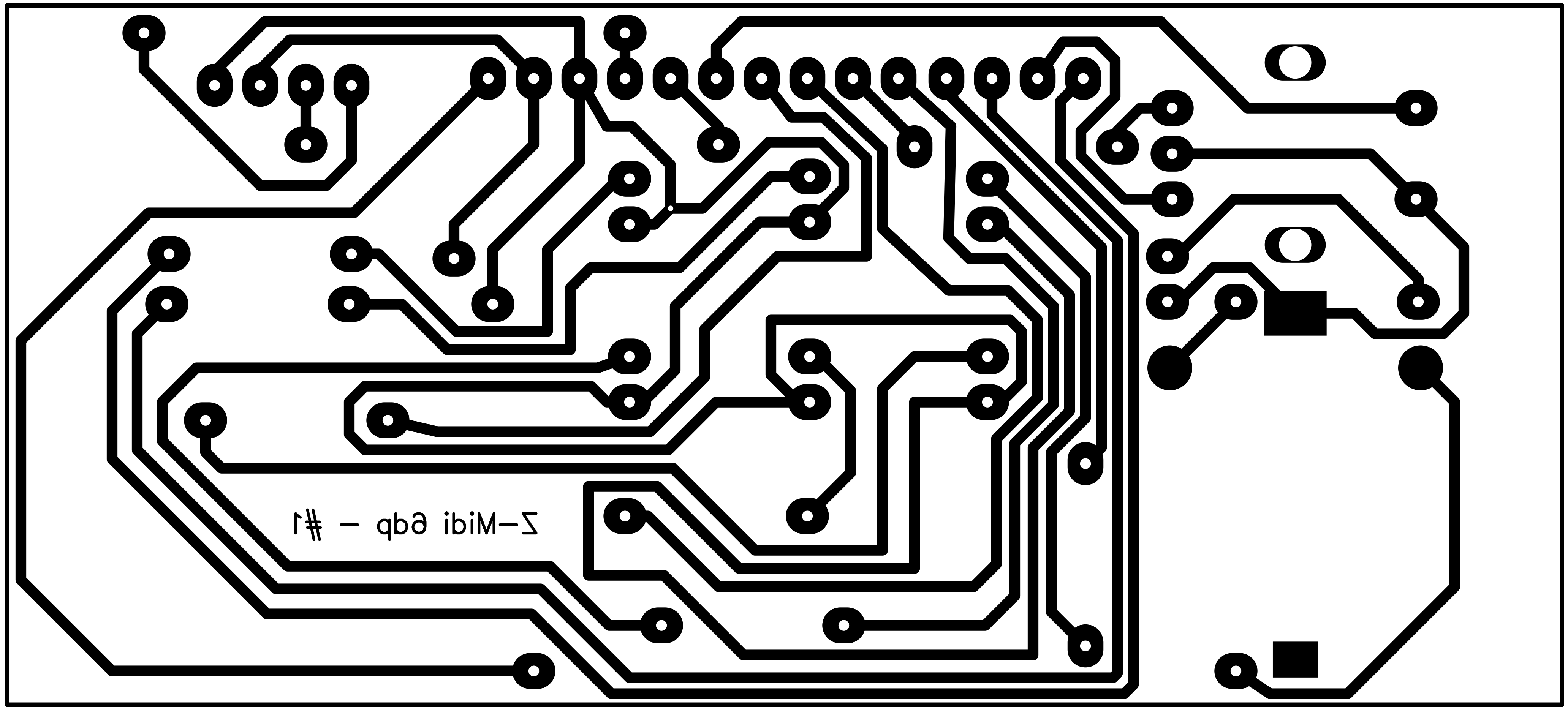
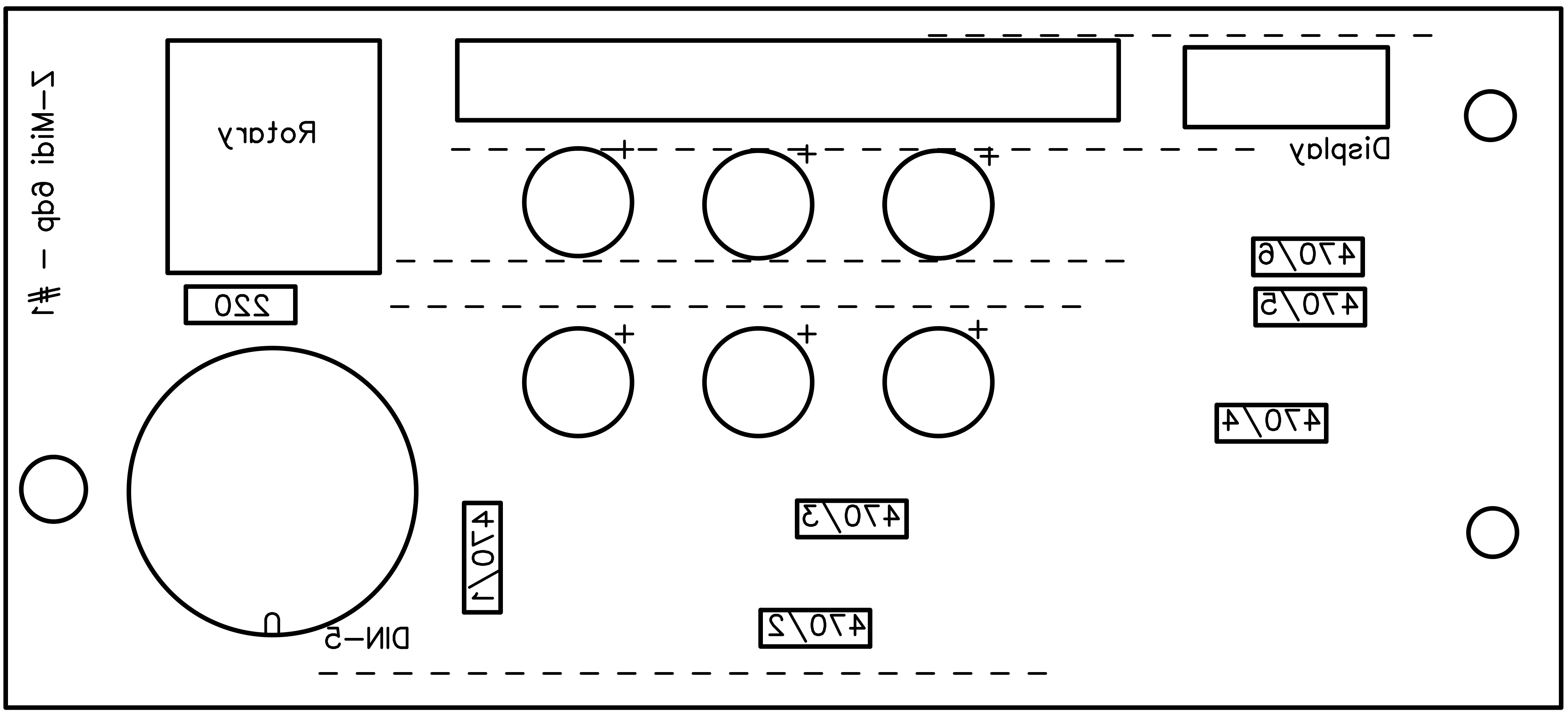
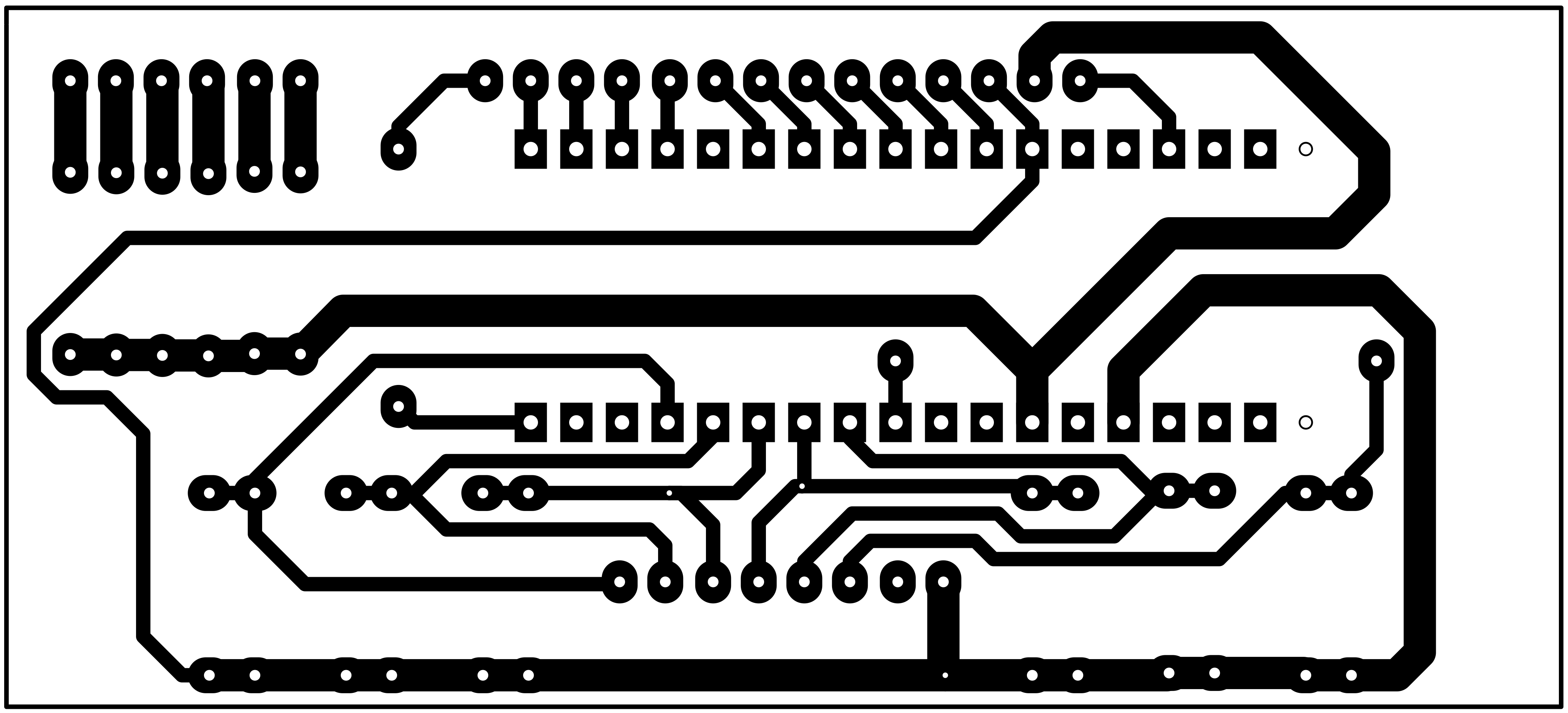
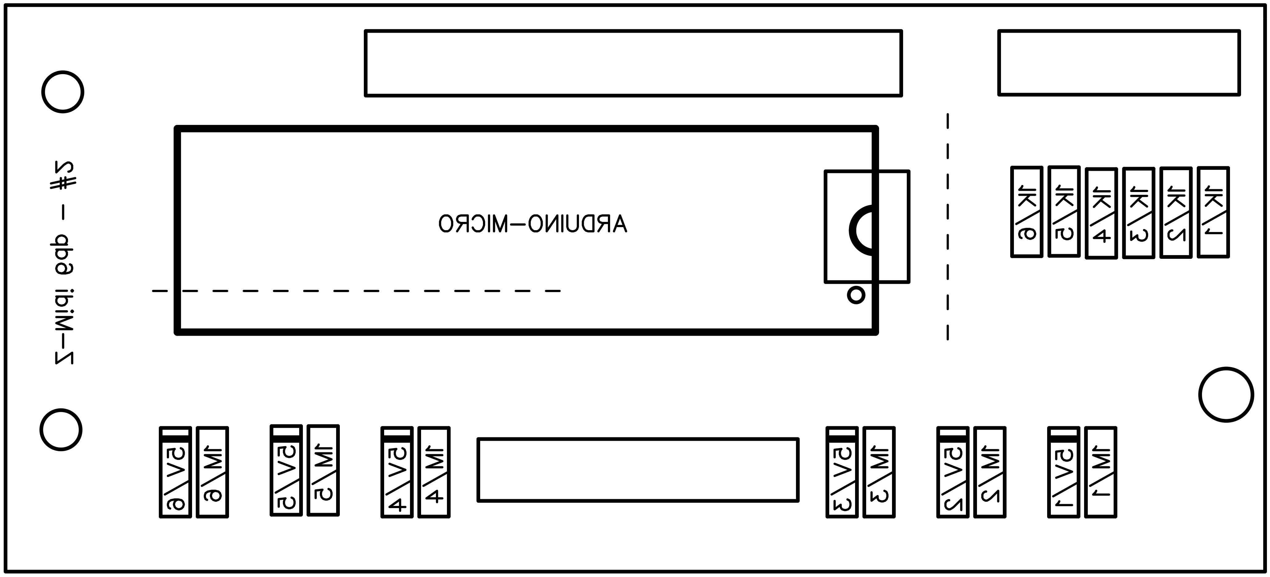
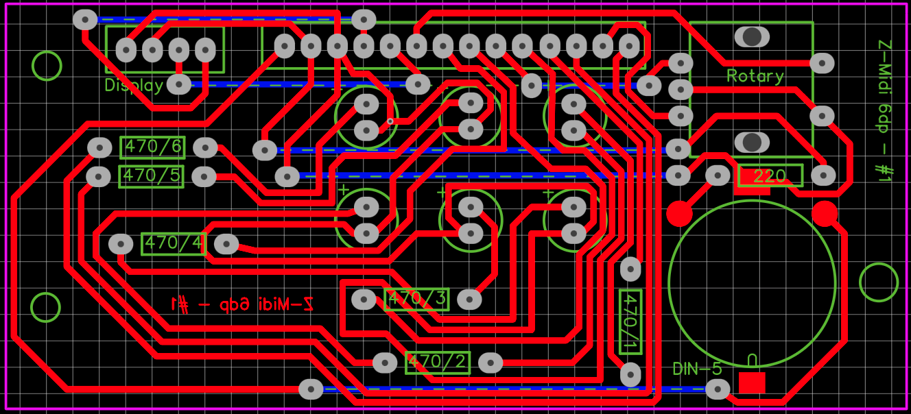
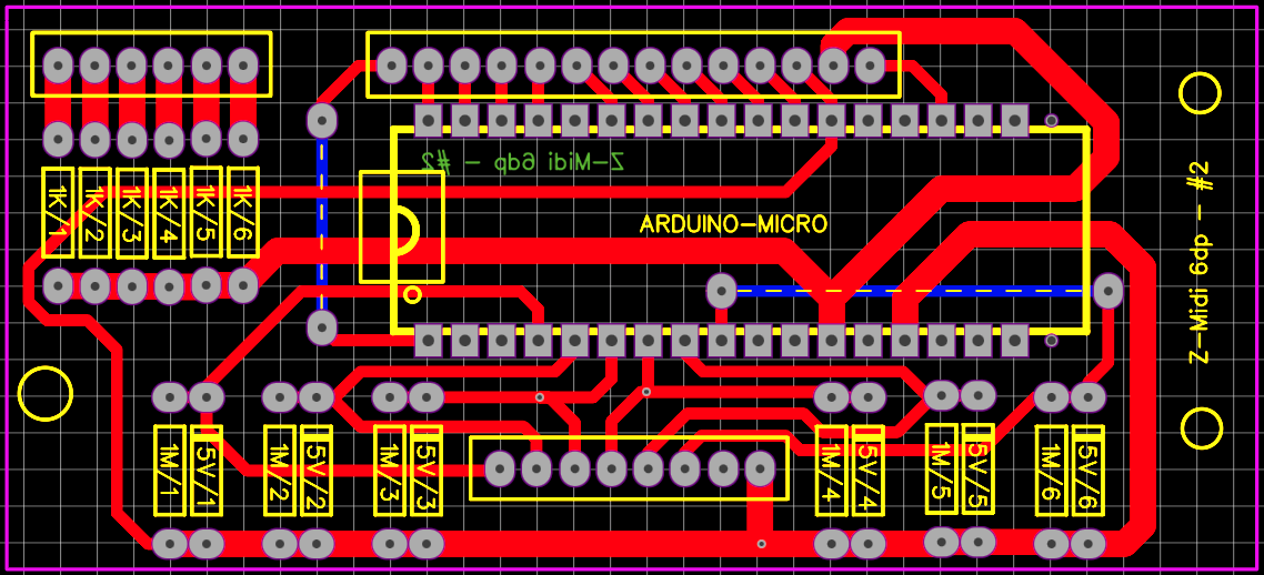
Is used single face PCBs for that reason I had to include a few wire jumpers (the dotted line ones) to solve routes for whole circuits. Below you have all files, components and solder faces, mirrored, for downloading and printing by the way of a laser printer on "yellow" or "blue" sheets. I used the yellow ones but they say the blue are better (but the price is significantly higher). When printing remember to disable toner saving settings, use instead 1200 dpi resolution to have deep real black result. The toner transfer process from magic sheets to PCBs is maden by the use of an hot iron... Printing on both faces, also on the components face, makes it easy to recognise positioning of items and even makes the project "professional".
Both PCBs are placed just behind the front panel to form a sandwich. Rear panel female jacks are connected by the way of coloured wires and connectors. Because the pins of the connectors are so long to touch the box, then you have to cut them before soldering wires. A short "pigtail" cable connects Neutrik reversible USB to Arduino micro USB.
The Tekal-31 aluminium box has its own front and rear plastic panels where you need to place the holes for components and screws, and make a window for the display. I redesigned these panels with FreeCad software to obtain two ".STL" files to be printed with a 3D printer. Less work for you and, I hope, a very good final result.
If you have a drum set rack you would like to mount the proper box support and a L-rod to place Z-MIDI6dp in your preferred position on your rack. I made pictures of these things above.
A step further: Make your own drum pad:It is quite easy to make your own, personalised, drum pad. I built an electronic cowbell using a real XDrum metal cowbell: make an hole for the 6.3mm female plug connector on the back, glue a 3.5mm piezo sensor inside on the top, solder the two wires (black to GND, red to the TIP), put some foam inside the cowbell to "mute" as much as possible the real sound but not to stop the vibration to reach the sensor when you hit the cowbell, glue a gummy sheet on outside top, connect it to Z-MIDI6dp and let starting music!
News and Improvements:- 28.03.2021: to complete the project I prepared two 3D .STL models at this link: https://grabcad.com/library/drum-set-midi-interface-box-panels-1 where you may download files regarding front and rear panels for this project to print by the way of a 3D printer.
Have fun!


Comments
Please log in or sign up to comment.