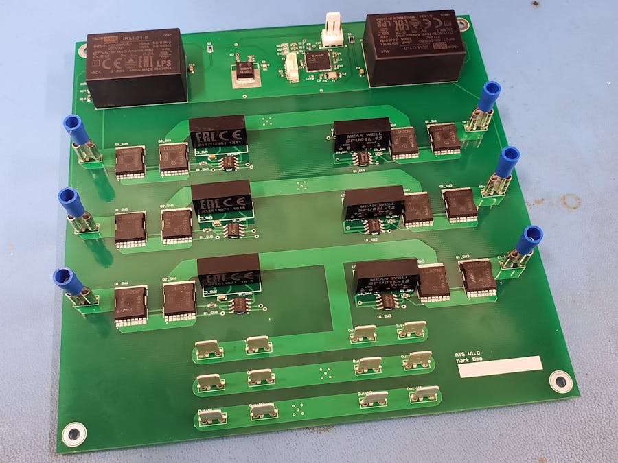
I have created the world's first open source automatic transfer switch (ATS), a device used by companies looking for the ultimate uptime for their data centers, like Facebook Google, and Amazon.
High uptime data centers have more than one power company providing power to them for redundancy (if one power company has a blackout or maintenance). An automatic transfer switch automatically swaps the devices connected to it between two power inputs.
I set out to create the world's first open source (MIT Licensed) Automatic Transfer Switch (ATS) using Infineon's new 600V CoolMOS™ C7 Gold superjunction MOSFETs. The low RDSon means that there is no need to parallel FETs to achieve the required current handling capacity (15+A), and the high breakdown voltage allows comfortable use with high peak voltages encountered in 120V/240V mains. In addition, the very low 1μA leakage current helps protect users in the event that they are servicing one of the utility inputs to the ATS while the other one is active.
How It WorksThe system has 3 main building blocks: the switching cells, the voltage input sensing, and the supervisor microcontroller.
There are 3 switching cells per AC input, one for the Hot, one for the Neutral, and one for the Earth.
The Hot sides of the AC cannot just be tied together because they may be out of phase and may have different amplitudes, up to ±10% from nominal.
The Neutral and Earth connections cannot be tied together because their voltage at the outlet (with respect to panel ground) depends on the circuit load. If, for example, Utility 1 had the majority of the load, the additional current on the conductor would cause it to rise with respect to the electrical panel, potentially up to the limit defined by NEC 2008: 210.19, 5% of the nominal voltage (in the case of 240V a loaded Neutral or Ground could rise as much as 12V above the panel Ground). In the event that the Neutral or Ground were not switched voltages high enough to present a hazard to people servicing one of the AC inputs could be present.
Switching CellThe switching cell consists of two back to back N-channel CoolMOS C7 MOSFETs to block current in both directions. However this topology presents some challenges, the MOSFETs source terminals are at line potential when they are on. To switch the MOSFETs, you need an isolated power supply and an isolated gate driver to turn the MOSFETs on and off.
I used an Infineon EiceDRIVER (specifically the 1EDI20N12AF) as my gate driver as it provides 1200V isolation for my design, plenty for operation up to 240V RMS and to accommodate line transients seen when inductive loads startup. I also have an isolated DC to DC converter to provide the 12V gate switching supply.
Because of the very low duty cycle of the switching (at most once every couple of seconds) there are no power dissipation concerns with the gate drivers or the gate resistors.
Voltage Input SensingTo sense the presence (or absence) of AC voltage on the input the open automatic transfer switch uses an AC optoisolator. AC optoisolator have there input diodes connected in antiparallel, so they are on for both cycles of the waveforms, with brief periods where they are off, the received as a logic level input to the Microcontroller. We can then detect when the AC is not present by checking the length of time the optoisolator output is low.
You can see that there are 3 current limiting resistor in series, this is due to the voltage limits of a single SMD resistor.
I chose a Microchip PIC32MZ for this project, it monitors the inputs and if the AC detect signal is interrupted for more than 2ms it switches what AC input it is using to the other one.
The PIC32MZ is powered by using diode ORing (using Infineon BAS3010A diodes) of AC/DC converters so it is powered no matter what AC inputs are active. The diodes feed into an Infineon IFX27001 3.3V linear regulator that supplies the microcontroller.
The microcontroller has 3 LEDs for indicating the status to the end user and a UART port for communicating with external equipment. Because the microcontroller is galvanically isolated from all the power circuitry, it is safe to interface it to external devices without fear of causing damage.
In the future, I plan to switch to the Infineon XMC1100 to drastically lower cost from ≈$10 to ≈$2.
LayoutThe layout of the Open Automatic Transfer Switch is critical to the safe operation of the device. The industry standard is IPC-2221B. The Open ATS is classified under IPC-2221B as category A6 which is "External Component Lead/Termination, Uncoated, Sea Level to 3050 m". The Open ATS can switch both 120 and 240 Mains, which have peak voltages up to around 340V, meaning the Open ATS falls into the 301V to 500V category. We can then look at the highlighted circle to find the clearance requirement of 59mil, to increase margin the Open ATS is designed with a clearance of 75mil.
All the voltage isolation components are rated for more than 1000V as required by UL 61010-1.
You can see the main isolation line highlighted in red in the picture below:
The open automatic transfer switch switches about half a power line cycle or around 3ms, much faster than required by the ATX (computer power supply) standard (see section 3.2.11: Voltage Hold-up Time, "[...] minimum of 17 ms"), allowing for equipment with less stringent build standards to be used. Like Oscilloscopes.


Comments
Please log in or sign up to comment.