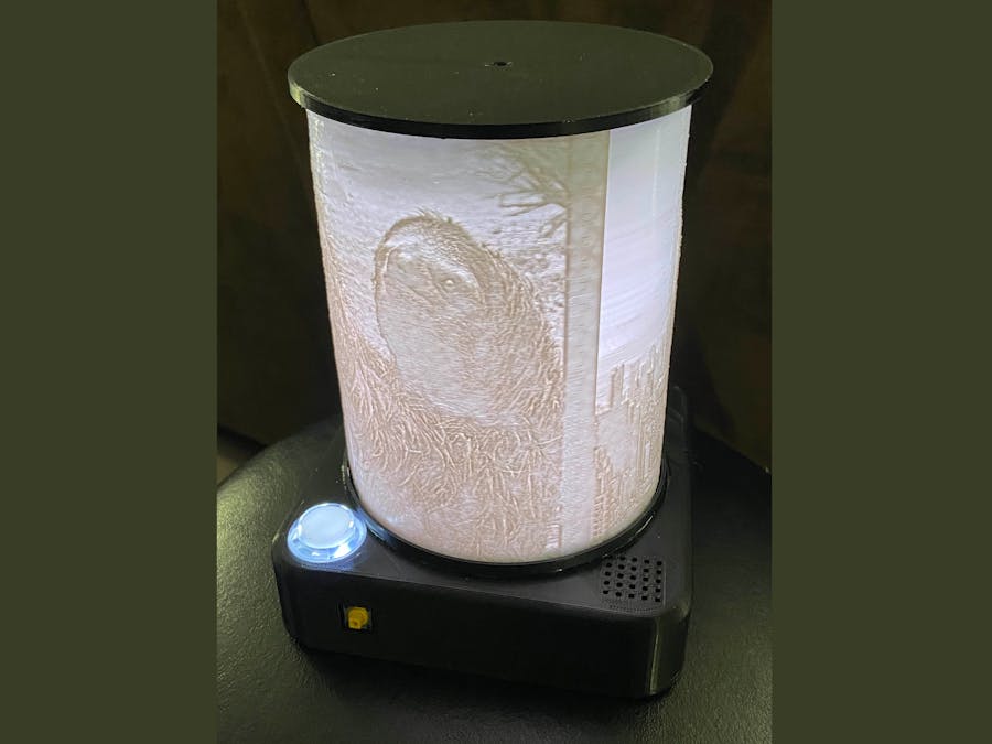
A lithophane is a translucent, etched object that once back lit will display an image. With 3d printers readily available it is easy to create a lithophane in a variety of shapes and sizes.
This project was intended to create a lithophane lamp, but rather then just be static I wanted the lamp to rotate creating a 360 degree lithophane "lamp shade" allowing all sides to be visible without the viewers having to move themselves.
After the initial design I decided it would be interesting to add a giant button, that when pressed would start a music and light show for everyone.
The project consists of 5 major components:
- The cylinder lithophane
- The electronics to run the lamp
- Gears and housing so the lithophane is spinning at a slow enough rate
- Enclosure to hold all the components
- The code making everything work
The lithophane we will be generating will be 152mm tall and require a circumference of 375mm, resulting in a diameter of 119mm. This information is important to ensure the image the lithophane is created from has the right length to width size ratio. The length becomes the height and the width the circumference.
The above measurements means the circumference to height ratio is 2.47. In practice this may vary depending on the thickness of the lithophane and accuracy of your 3d printer.
I put three images on my lithophane but the important part is to ensure the width is 2.47 times the height. I included grey bars between the images (and on the ends) to create some separation between the pictures.
To generate the lithophane I used this site https://3dp.rocks/lithophane/
Once on the site you need to set the style to "Outer Curve". Then go under "Settings" and set "Maximum size" to 375mm and "Curve" to 360. Use the images tab to upload your image and wait while the site generates the lithophane. The download button will then download your lithophane STL.
I used Ultimaker Cura to print my lithophane but you can use whatever tool your are most comfortable with. Make sure you have set your infill to 100%. This will create the best looking lithophane. At this step you can ensure your height and width (diameter) measurements are correct.
Be warned, it took me just over 40 hours to print the lithophane I made at high quality. I suggest printing a test at lower quality, and stopping the print after a couple centimeters have printed to ensure it fits properly.
Immediately after you have finished your print you can put a light source inside to see a preview of how it will look.
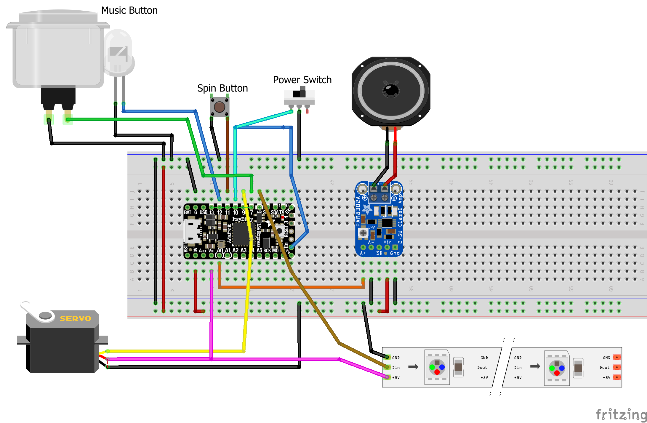
The heart of the lamp is an Adafruit ItsyBitsy M4. This is a powerful and useful board that is great to drive items like neopixels and servos. It has a special 5V output pin to provide those devices with more voltage.
The ItsyBitsy has attached to it:
- Audio amplifier (which is turn hooks to the speaker) - hooked to A0
- Power switch - hooked to D10 and Enable
- Mode/Spin button - to toggle to LEDs on, and turn the servo - hooked to D11
- Arcade button - to start the musical show - button hooked to D7 and LED to D12
- Neopixels - hooked to D5
- Servo - hooked to D9
Wiring all the grounds together is tricky as there are so many. I soldered all the grounds to a piece of wire that I then covered in electrical tape after.
As some of the components stretch through the lid of the base it can be beneficial to use connectors (like JST) to allow them to be disconnected if required. It saves the effort or desoldering wires if something has to move (a lesson I learned the hard way!).
This is is particularly useful for the servo, neopixel and arcade button wires.
CodeThe code is fairly straight forward; starts with configuration and setup and then the main loop that operates the lamp. The lamp when running watches for one of the two buttons to be pressed. The smaller mode button will alternate turning the LEDs on, enable the lithophane to spin, and shutting it down. The arcade button when pressed will trigger a timed animation show.
SERVO_SPEED = 0.07 # speed to rotate the servo at
LED_FLASH_TIME = 30 # how long to flash the arcade button for
The servo speed controls the rotational speed of the lamp. The flash time controls how long the arcade button flashes for when not in use. If it always flashes it does get annoying!
# Set up the servo
lid_servo_pwm = pulseio.PWMOut(board.D9, frequency=50)
lid_servo = servo.ContinuousServo(lid_servo_pwm, min_pulse = 420, max_pulse = 2500)
The servo setup may also need slight changes. The min_pulse and max_pulse have to be set to ensure the servo will not move when it should be stationary. The default values should usually work.
# Set up the audio playback
audio = AudioOut(board.A0)
mp3files = ["dance-mono.mp3"]
The mp3files is the MP3 that will be playing when the arcade button is pressed. As space is sparse on these devices the MP3 will have to be short and compressed down in quality. There is no point in using stereo either as the speaker is mono. I was able to have a 5 minute MP3 fit with enough compression. Use a tool like Audacity to edit the MP3.
# define animation for the arcade button
rainbow = Rainbow(pixel_wing_vertical, speed=0.1, period=2)
There is a section defining all the animations that will play when the Arcade button is pressed (headed by a comment saying "# define animations". These are the raw animations that will be played and not the sequence and timing that will be used.
All the animations used come from the Adafruit CircuitPython LED Animation library except Volume and TimedAnimatedSequence. I wrote those two based on the Adafruit library.
# modes the program can be index
MODE_OFF = 0    # nothing running
MODE_LIGHT = 1  # neopixels lit only
MODE_SPIN = 2   # neopixels lit and servo moving
MODE_MUSIC = 3  # music show is on
MODE_MAX = 3    # only the arcade button will get to MUSIC
The main loop is a while loop that lasts forever. It checks the buttons and changes the current mode depending on the user's actions.
The only mode of interest is MODE_MUSIC where the animation sequence plays.
The heart of this is setting up the TimedAnimationSequence:
animations = TimedAnimationSequence(
                solid, 12,
                loud, 20, # 32
                rainbow, 16.5, # 48.5
                rainbow_comet, 14, # 1:02.5 62.5
                rchase2, 36, # 1:38.5 98.5
                rainbow, 16.5, # 1:55 115
                rainbow_comet, 14, # 2:09 129
                loud, 33, # 2:42 162
                clear_sparkle, 16, # 2:58 178
                rcomet2, 14, # 3:12 192
                rainbow_sparkle, 32, # 3:44 224
                rchase2, 16, # 4:00 240
                loud, 37, # 4:37 277
                clear_sparkle, 5,
                solid, 60,

                auto_clear=True,
                auto_reset=True,
            )
Each line defines which previously defined animation to play and for how long. I used comments to keep track of the running time to help sync the animations to the music.
Gear HousingThe gear box consists of several gears held without a housing. You will have to print two of the ComboGear.stl and one of the GearBox Base.stl, GearBox Lid.stl, Spur Gear.stl and Drive Gear.stl. The drive gear will fit on the servo later.
The gears sit loose in the base of the box and the lid will hold them all in place. I suggest holding the lid in place to ensure everything freely turns before you epoxy the lid to the base. With 3d printed parts you may want to spin things for a while to loosen them up and ensure they work properly.
The enclosure assembly consists of three main parts:
- The stand with the gear box and servo case
- The base of the lamp holding the electronics and buttons
- Lithophane, the lid on top, and attaching everything together
Stand, Gearbox and Servo Case
These three pieces are attached together with epoxy. There is a small raised dimple on the top of the stand piece that matches with a small hole in the bottom of the gear box. The gears line up with the center of the stand piece.
To attach the servo case, insert the servo with the attached drive gear. Use this to determine the proper height for the servo case. The drive gear should cleanly mesh with the lower gear of the gear box. Important it cannot mesh with both gears or nothing will move! The servo case is also attached with epoxy.
LampBaseand Buttons
The base contains the electronics to run the lamp. There are holders for the ItsyBitsy M4 and the audio amplifier, though I suggest using hot glue or tape to ensure they stay in place. The power switch and mode button to turn the lamp on and off are mounted in the side of the case. I suggest hot glue again to hold them in place.
The speaker and optional battery (which I later removed) sit in the empty area of the case and again should be glued down.
The arcade button that turns on the light show screws into the base lid piece. Using a connector on the wires will allow it to be hooked up easier, otherwise you will have to solder the button to the ItsyBitsy after it is screwed in.
The lid snap fits to the base for removal if neceesary.
Lithophane, Lid and Attaching Everything
Once the base is set the next step is to attach the gear box stand. It is attached to the base lid in the center with epoxy. The servo case is towards the back of the base where the power switch is located.
After the stand is glued, the neopixel LEDs are attached to the sides of the stand. Again in this step a connector at the end of the neopixels is recommended rather then direct soldering.
Many neopixels have a plastic coating on them that makes gluing them difficult. Your options are to remove the plastic and glue to the strips, or use a generous amount of hot glue (and even then it gave me troubles!).
Once the base lid is attached you need to epoxy the lithophane to the lithophane lid. This allows the servo and gearbox to rotate the entire assembly in unison.
After the glue has set the gear at the top of the gear box inserts into the slot on the bottom of the lithophane lid. There is a screw hole (M3 size) to held secure the lid to the gear.
And with that you are ready for operation!
ResultWatch the lamp in action!


Comments
Please log in or sign up to comment.