Please note: I still consider this a PROTOTYPE. This project will get a second version in order to fix some problems that have arisen with this version. If you want to build something like this, please read the entire story and my commentary about the problems that I have experienced.
This was my first major electronics project that wasn't building a computer. Looking back as I write this, I will be avoiding some of the design choices I made for this project in future projects.
I originally designed this to be a learning experience to teach myself more about electronics, especially audio amplifiers. I started designing and researching this mid-way through my senior year of high school, and I didn't "finish" it until a few days before I left for college.
My design goal for this project was to make a decently powerful amplifier that could accept either balanced or unbalanced inputs and had different types of outputs as well.
I have linked datasheets of the amplifier board and main power supply below so you can look at in-depth specs and to keep this explanation shorter.
Some info on parts:Amplifier/preamps:
- Main amp: 3e Audio's version of the TPA3255 amp board sounds amazingly clear and precise for the price. This board is rated at 2x260W @4Ohm <1% THD. Its small, has an inaudible noise floor, has extremely low THD into its rated speaker load, and is very efficient. 3e Audio also offers a 1x480W @4Ohm option as well.
- Unbalanced preamp: This is a preamp board made by Douk Audio that originally came with a NE5532 OpAmp. I replaced the NE5532 with a LM4562 OpAmp. They are pin compatible so it's a drop-in replacement (just make sure you get the orientation correct).
- Balanced preamp: I used 2x AD828 preamps, one for each balanced channel.
Please note: in some earlier pictures, you can see different balanced preamps (the black ones in the same spot in the case as the AD828's). I did not use those because I fried one by accidentally overvolting it during testing.
Power supplies:
- Main Supply:The SMPS600RS from Connexelectronic is a very low noise switching power supply that can provide a continuous 600W. They are sold with different output voltages, and the 48VDC version is the closest version to the maximum 50V that the TPA3255 board can accept. This power supply also has an auxiliary 12V 500mA output. I used this to power the fan and relays. I would recommend using a separate 12V power supply if you need to power more than some relays and a fan off of 12V. I'm drawing near the 500mA limit with the 8 channel relay module on and the fan on high. Something unexpected that I noticed with the auxiliary supply is that if the power gets disconnected from the main amp, or the main amp is put into reset, the auxiliary 12V rail sort of browns out which causes the relay boards to flicker on and off.
- PreampSupply: This MeanWell +/-15VDC supply is used for the preamps. It has a maximum output of 1A on each rail, which should be plenty for preamps, and it has reasonably low ripple and noise. You could probably find a better supply if you really wanted one, but I have been happy with this supply.
EDIT: I did not realize the preamp board accepts an AC input and rectifies it. For some reason I thought it was a +/-15VDC input. Instead of this SMPS, use an appropriate transformer instead. I have not noticed any problems using the meanwell supply to power the preamp, and it can drive the amplifier up to clipping just fine. However I would really recommend avoiding this mistake and using a transformer instead. Thank you to Saravanan J for pointing this out!
I/O:
- BalancedInput: Here I used XLRs since those are standard in the equipment I use. You could also swap them out with 1/4" TRS jacks.
- UnbalancedInput: I just used a 3.5mm TRS jack so I could use this amp with almost any consumer device made within the last few decades.
- SpeakonOutputs: I used a pair of 4-pole speakons with the +/-1 poles on each in use and another 4-pole speakon with all four poles used. This should ensure better compatibility with various wiring of speakon connections in speakers.
- SpeakerBindingPosts: These are pretty standard in consumer amplifiers. They accept banana plugs or bare wire.
Case:
- I made a temporary case out of wood to prototype the amp. The end goal for a case is for it to fit in a 19" rack as a 2U height.
- The current 'case' measures 17.5in (length) x 3.5in (height) x 12in (depth).
Misc.:
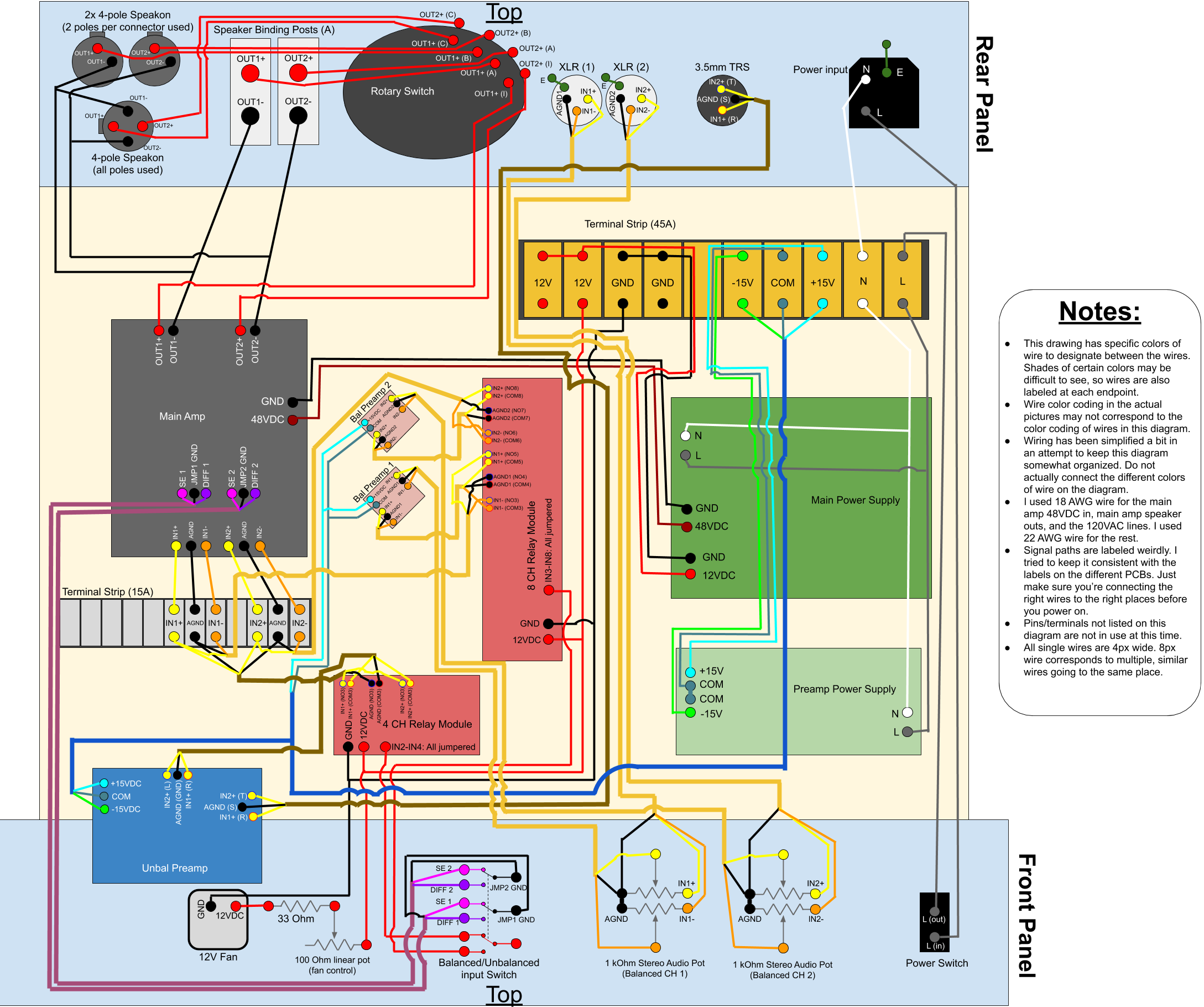
- Terminal strips: I used the small terminal strip to make it easier for me to hook the input signals from the preamps to the main amp. I used the larger terminal strip to hook the power side wires together. Power side wires include 120VAC, +/-15VDC power supply output, and 12VDC from the main power supply's aux power out. I know a 45A rated terminal strip is overkill for the amount of current that would ever come through these terminal strips. If you were to just use 15A rated strips, you should be fine.
- Rotatory switch: I wanted to be able to use a rotary switch to switch outputs, and this was rated for a high enough voltage/current that I was comfortable sticking it on an amplifier output. This switch is massive and has way more output positions than I will ever use. For some reason I didn't think of using a smaller rotary switch to control relays to change outputs until well after I got the switch.
- Relays: These relays are used to switch each individual input wire. All of the balanced inputs go to the 8 channel board and all of the unbalanced go to the 4 channel board. This method leaves empty channels and is not as efficient as other methods. The relays are located after the preamps in the signal chain.
- InputSelectorSwitch: This switch is an ON-ON 3PDT switch. This switch handles the input jumpers on the amplifier and the control signal for the relays.
Approximate steps:You don't necessarily have to follow these steps in this order. This is just the way I did it. I unfortunately did not take many pictures of the build process, but I did attach a wiring diagram. Also, I feel like I have to further warn you that playing with AC wall power is a TERRIBLE idea if you don't know what you're doing. Don't do this if you are not comfortable with higher voltage electronics (as compared to the 5V/12V electronics that I see commonly on this site).
1. Start by laying out all of the components in the rough locations of where you want them. I placed them where I thought would be best to reduce the amount of wire used.
2. Unscrew the metal cover on the unbalanced preamp and replace the NE5532 opamp with the LM4562. Make sure to put the cover back on.
3. Mark all of the mounting holes to drill in the "case" and use the standoffs and M3 screws to mount all of the boards and connectors.
4. Next wire the AC power side using the 45A terminal strip and ring connectors to make multiple connections to the input hot and neutral. Make sure to put a power switch directly on the incoming input live and to provide AC power to both power supplies.
5. Wire the 48V output of the main power supply directly to the power input of the main amp.
6. Then, wire the +/-15V to all of the preamps using the 45A terminal block to make multiple connections. I ran one wire for the COMM pins on the power supply since those pins were already connected. The unbalanced preamp takes +/-15V while the balanced preamps only take +15V.
7. The final power side wiring that needs to be done is the 12V from the auxiliary power of the main power supply. Using the 45A terminal block as an intermediate connection point, wire the power to the relay boards, relay signal, and fan. The fan 12V is connected to a 33 Ohm resistor to limit the current to the fan as well as a 100 Ohm linear pot to control the speed. GND is directly connected to the fan so the fan cannot turn all the way off. The 12V used to signal the relays open/closed should be connected to one of the poles on the the 3PDT toggle switch. One of the outputs of the toggle goes to one relay board and the other output should go to the other relay board. The signal inputs of each relay board are jumpered together with small, solid core wire in the shape of a "U."
8. Moving on to the signal wire, the unbalanced input is the simplest to wire, so I chose to begin there. Run the wires from the 3.5mm input to the unbalanced preamp. From there, each wire of the preamplified signal should connect to the separate COM pins on the 4 channel relay board (only 3 of the 4 channels will be used). Then connect the NO pins of each used relay board channel to the respective pins of the input on the amplifier board. Connect the signal GND to both amplifier input GNDs, the right channel to one of the amplifier IN+ pins, and the left channel to the other IN+ pin. I used the 15A screw terminal strip as an intermediary to connect multiple wires together.
9. The unbalanced wires should first be connected to the 2x 1 kOhm log pots. Each pot should only take one channel of audio input with the hot wire and the cold wire on separate poles/decks of the same pot. The GNDs on both poles/decks of the pots can be wired together. Wire the output of the pot to the balanced preamps, then the output of the balanced preamps to the 8 channel relay board the same way that the unbalanced signal was wired. Finally, wire the NO pins on the relays to their respective locations on the main amplifier using the 15A terminal strip as an intermediary connection.
10. Next, wire the jumpers from the main amp to the 3PDT toggle switch. One channel should go on each pole of the toggle switch, with the middle pin from the jumper being common and the two other pins matching with the side on which the relay board signals were wired. I had all of the unbalanced switching signals on the top pins of the toggle and the balanced on the bottom pins. The inputs would then go in the middle.
11. Wire the "-" of each channel of the main amp output to the "-" of each output. I wired them to the binding posts then wired the other outputs off of the binding posts since they had more room to solder wires. Wire the "+" of each output channel to one set of the poles/decks of the rotary switch. Off of each set of rotary switch outputs/throws, wire each corresponding speaker output.
12. Check that all connections are secure. I would recommend using a multimeter with a continuity test to verify all of the wires are connected properly and to the correct locations. Check that you have a fuse with a sufficient rating inserted in the main AC power input. Check to make sure you do not have any bare wires touching each other. Bare wires or sections of wire are probably a bad idea anyway, so cover those with electrical tape or heat shrink.
13. Test start the amplifier. Be prepared to (safely) pull the plug if something starts to go wrong. Check that LED indicators on the main power supply, the relay boards, and the main amplifier are on.
14. Finally, if everything seems to be working fine, plug in an input source and speakers, and test with some audio. If all goes well, you're done and you can start listening!
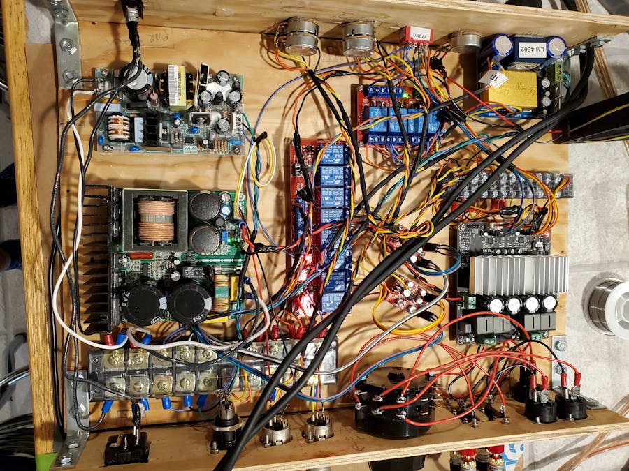
1 / 2 • The amplifier with only a few wires hooked up. Also, notice that I have other preamps in the build in these pictures, and the balanced volume pots have not been put in yet.
Here is the amp fully assembled and wired. The larger black cables running diagonally across the amp are XLRs.
Problems:
- Earthing is nonexistent in this right now. It will be added once the case is made of metal. This causes some weird noise issues when you touch the volume pots as they are not properly earthed to the case.
- When turning off the amp in balanced mode, a lot of popping occurs. I suspect this is caused by the balanced preamps turning off before the amp does. This is a pretty bad issue that will be fixed in version 2.
What I would do differently/Recommendations:
- I would recommend a much smaller rotary switch connected to relays to handle switching to different outputs. This switch was way too large and had way too many outputs for what I needed.
- If you only need balanced or only need unbalanced inputs, this whole design can be much simpler. All of the components used to switch inputs and the preamp(s) for the other input type can be removed.
- If you only need one type of output, the design can also be simplified a bit. You could remove the annoying rotary switch (or relays like I suggested earlier) and the other outputs.
- Both the balanced and unbalanced inputs can technically be on the same set of relays with one set on the NO pins and the other on the NC pins.
PlansforVersion2:
- A decent amount of this is getting redesigned. I'm completely getting rid of the annoyingly-large rotary switch, and I will be simplifying a good chunk of the wiring.
- The inputs are all going to go on the same relay board with the unbalanced on the NC pins and the balanced on the NO pins.
- I will be scrapping the balanced preamps in favor of using another LM4562 preamp. Hopefully this will eliminate the popping on power-off issue
- I am going to be adding an arduino to control many aspects of the amp such as the switching of inputs and outputs via relays. I will also be adding a small screen to display a realtime audio analyzer.
- The fan will have a connector so I can disconnect it when taking the amp apart.
- I will be designing a metal 19" rackmount case to replace the wooden one I threw together. Whenever I do that, I will be sure to include a CAD file. That will be after building version 2.
- I'll be taking new pictures of the amplifier and the build process.
ConclusionOverall, I have been very impressed with the performance of this amplifier. I tested it with a mid-range set of bookshelf speakers that I had previously been using with a mediocre 2x120w amp, and I was blown away by how good they sounded with this amp. Everything sounds clear and precise with no noticeable distortion, even with the level close to clipping. Neither the power supply nor the amplifier heat up much. Their heatsinks never get warm enough for me to not be able to touch even when running near clipping for multiple hours. Also, the noise floor is almost nonexistent. I have to put my ear less than an inch from the speaker driver to be able to hear any amp hum.
Thanks for reading, and let me know if anyone tries building this for themselves!


Comments
Please log in or sign up to comment.