This is a simple tutorial to create an EMF detector. You can use Arduino for this job, but is better use a microcontroller called ATtiny85. It is possible program it throe the Arduino interface.
What is a Magnetic Field [from Wikipedia]An electromagnetic field (also EMF or EM field) is a physical field produced by electrically charged objects. It affects the behavior of charged objects in the vicinity of the field. The electromagnetic field extends indefinitely throughout space and describes the electromagnetic interaction. It is one of the four fundamental forces of nature (the others are gravitation, weak interaction and strong interaction).
The field can be viewed as the combination of an electric field and a magnetic field. The electric field is produced by stationary charges, and the magnetic field by moving charges (currents); these two are often described as the sources of the field. The way in which charges and currents interact with the electromagnetic field is described by Maxwell's equations and the Lorentz force law. From a classical perspective in the history of electromagnetism, the electromagnetic field can be regarded as a smooth, continuous field, propagated in a wavelike manner; whereas from the perspective of quantum field theory, the field is seen as quantized, being composed of individual particles.
Bill of MaterialsThe materials of this project are:
- Protoboard
- Breadboard
- Attiny85
- 3mm leds
- CR2025 Battery
- CR2025 Battery case
- 40 Ohm resistors for leds
- 1 MOhm resistor for probe
- Jumper wires
Many of these components are in this KIT
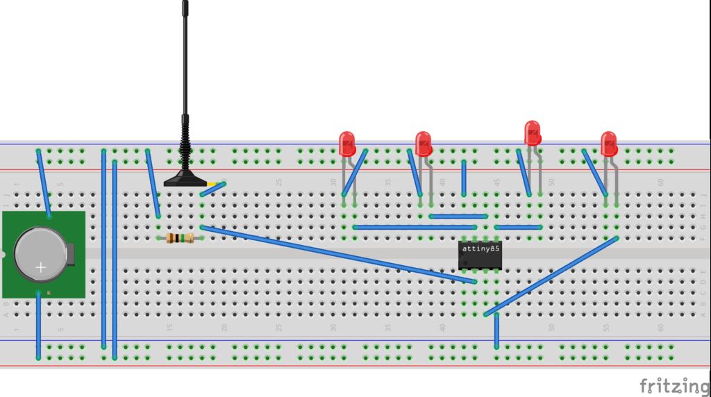
Step 1: The circuitFirst step is create a circuit on the breadboard. Use a breadboard like in photo and try the circuit before solder it on protoboard. After the test you can use a protoboard to connect the attiny85 to LEDs and antenna.
For upload the code on Attiny85 you can use this shield and a programmer, or your Arduino UNO.
Step 2: The codeSee the code also on GitHub: https://github.com/masteruan/Attiny85_EMF
// EMF Detector Attiny85 and 4 led v1.0// 23.10.2015// original code/project by Aaron ALAI - aaronalai1@gmail.com// modified for use by Giovanni Gentile - giovanni@0lab.it
#define NUMREADINGS 15 // Number of readings
int senseLimit = 15; // Raise this num to decrease sensitivity int val = 0;  int antenna = A2;
int LED[] = {2,0,1,3}; // After verify the position of red green and yellow leds
// Variables for smoothing
int readings[NUMREADINGS];
int index = 0;
int total = 0;
int averange = 0;
void setup() {
pinMode(2, OUTPUT);
pinMode(0, OUTPUT);
pinMode(1, OUTPUT);
pinMode(3, OUTPUT);
pinMode(A2, INPUT);
// Test leds on start
for (int i=0; i<4; i++) {
digitalWrite(LED[i],HIGH);
delay(500);
}
for (int i=0; i<4; i++) {
digitalWrite(LED[i],LOW);
}
// Initialize all the readings
for (int i = 0; i < NUMREADINGS; i++) {
readings[i] = 0;
}
}
void loop() {
int val = analogRead(antenna);
if(val >= 1){
val = constrain(val, 1, senseLimit); // turn any readings higher than the senseLimit into the senseLmit
value     val = map(val, 1, senseLimit, 1, 1023); // remap the values
total -= readings[index]; // subtract the last reading
readings[index] = val;    // read from the sensor
total+= readings[index];  // add the reading to the total
index = (index + 1);      // advance to the next index
if (index >= NUMREADINGS)       index = 0;
averange = total / NUMREADINGS;
if (averange > 50) {
digitalWrite(2,HIGH);     }
else {
digitalWrite(2,LOW);     }
if (averange > 350) {
digitalWrite(0,HIGH);     }
else {
digitalWrite(0,LOW);     }
if (averange > 750) {
digitalWrite(1,HIGH);     }
else {
digitalWrite(1,LOW);     }
if (averange > 950) {
digitalWrite(3,HIGH);     }
else {       digitalWrite(3,LOW);     }
}
}Go to www.arduino.cc
Go to Download (https://www.arduino.cc/en/Main/Software)
And select the previous installation of Arduino IDE 1.0.6. This is very IMPORTANT because with the new version of Arduino IDE is impossible to program the Attiny85. After the installation of attiny85 package you can select the Attiny models.
After installation of IDE you can programming the Attiny85 by your Arduino UNO. Then following this tutorial https://www.instructables.com/id/How-to-program-the...
Step 4: Final ResultI have used a perfboard and 4 little leds. The result is more pretty. A micro, open source, portable and geek EMF detector.
The electromagnetics fields now are visible. I use this in my courses. With this I demo the force of electromagnetic field. You can use this EMF detector, near a microwave or fridge or a big power supply. Also the ventilator generate a big electromagnetic filed.


Comments
Please log in or sign up to comment.