


Hardware components | ||||||
 |
| × | 1 | |||
 |
| × | 1 | |||
 |
| × | 1 | |||
Software apps and online services | ||||||
 |
| |||||
Hand tools and fabrication machines | ||||||
 |
| |||||
Required Hardware
Before getting started, let's review what you'll need.
- Raspberry Pi 3B/B+ (Recommended) or Pi 2 Model B (Supported).
- MATRIXCreator - Raspberry Pi does not have a built-in microphone, the MATRIXCreator has an 8 mic array - Buy MATRIX Creator.
- Micro-USB power adapter for Raspberry Pi.
- Micro SD Card (Minimum 8 GB) - An operating system is required to get started. You can download Raspbian Stretch and use the guides for Mac OS, Linux and Windows In the Raspberry Pi website.
- Micro-USB Cable
- A USB Keyboard & Mouse, and an external HDMI Monitor - we also recommend having a USB keyboard and mouse as well as an HDMI monitor handy. You can also use the Raspberry Pi remotely, see this guide from Google.
- Internet connection (Ethernet or WiFi)
- (Optional) WiFi Wireless Adapter for Pi 2. Note: Pi 3 has built-in WiFi.
- A relay board like this one
- two diode (optional)
OR
- A MATRIX Kit
- A relay board like this one
On your personal computer, you'll need the following:
- Node.js: Dependancy for Sam CLI Tool.
- Etcher.io: To easily flash our Raspbian Stretch image.
- Snips' Sam CLI Tool: Creates & manages Snip assistants on your Raspberry Pi. (Windows users may need to run their terminal session as Administrator when installing the Sam CLI Tool)
You'll also need a registered snips.ai account.
Let's Get StartedIf you haven't already, be sure to setup your Raspberry Pi with your MATRIX Device.
You will need to follow the steps below in order for Snips to work on your Raspberry Pi.
- Install MATRIX Lite on your Raspberry Pi (Be sure to setup MATRIX HAL first)
- Configure Snips.ai
By this step, you should have a snips.ai account and the Sam CLI Tool Installed.
From your computer's terminal, sign in through the Sam CLI Tool.
sam login
Connect to your Raspberry Pi. When prompted for a username & password, you can press the enter key to insert the default Raspberry Pi credentials.
sam connect YOUR.PI.IP.HERE
Check if Snips is running.
sam status
# Example output
# If all services are not (running), use the `sam init` command
Service status:
snips-analytics .............. 0.60.10 (running)
snips-asr .................... 0.60.10 (running)
snips-audio-server ........... 0.60.10 (running)
snips-dialogue ............... 0.60.10 (running)
snips-hotword ................ 0.60.10 (running)
snips-nlu .................... 0.60.10 (running)
snips-skill-server ........... 0.60.10 (running)
snips-tts .................... 0.60.10 (running)
Begin viewing the Snips event stream. This will let us verify if your intents are being heard.
sam watch
Sign into your Snips.ai and create an assistant. Feel free to choose the wakeword you want. Once created, make a new application named thermostat.
Intents are what Snips uses to handle user requests. For this Assistant, we'll start by creating an intent for controlling the relay.
Create a new intent called ThermostatState for your Thermos app.
Once you've defined your intent, you need to extract what the user wants to do with their thermostat. This is where slots come in.
Create a new slot called readWrite and a custom slot type with the same name.
This slot will be used to both tell the temperature and set the temperature.
Create a second slot with the built in slot type Number and with the same name.
Create example sentences containing the words under synonyms and value and numbers such as the examples below. Highlight these words in your example sentences to assign them to your recently created readWrite/Number slot.
Be sure to save!
Button is on the bottom right corner of the page.
You can now deploy your assistant! On the bottom right of the page will be a Deploy Assistant button.
If you don't see Deploy Assistant, increase your web browser's width.Use the Sam CLI Tool to deploy the assistant to your Raspberry Pi. Below is an example of the command to use.
Congrats on deploying your Snips assistant!
5. Creating assistant.js (Raspberry Pi)This step will go show you how to setup a MATRIX Lite project with Snips. assistant.js will be used to listen and respond to events from your Snips assistant
These files will go on your Raspberry Pi.
Create 2 new JavaScript files.
mkdir lite_js
cd ~/lite_js
touch assistant.js relay.js
MQTT must be installed and used to listen in on events from Snips.
npm install mqtt --save
With all the required dependencies installed, you can now open assistant.js & relay.js (we like using VSCode through CyberDuck.io).
Copy & paste the code below for each of the two files.
relay.js includes the code required to turn the relay on and off, control the leds, and collect the temperature. This relay will control power to the thermostat.
By default the temperature is read and set in Celsius. To convert to Farenheit, use the equation (C x 9 / 5) + 32 = F on the equation used to assign the currentTemperature variable its value, i.e.
Set the lowestTemperature and highestTemperature variables to the lowest and highest temperature you want the thermostat to go to; this also sets the relative number of leds that turn on when displaying the temperature.
(((humidityTemperature + pressureTemperature)/2 - (a constant you can determine)) x 9 / 5) + 32
const matrix = require("@matrix-io/matrix-lite");
var methods = {}; //methods object
var relayPin1 = 0;
var relayPin2 = 1;
//initialize the global variables//
var currentTemperature = 20; //store the current temperature
//create the offset temperatures (usually 1 degree above and below the desired temperature)
var temperatureOffset1 = 0;
var temperatureOffset2 = 0;
//create variables that hold the humidity and pressure temperature sensor readings
var humidityTemperature = 0;
var pressureTemperature = 0;
var waitingToggle = false;
var lowestTemperature = 10; //holds the lowest temperature wanted (be mindful of farenheit /celsius conversions)
var highestTemperature = 30; //holds the highest temperature wanted (be mindful of farenheit /celsius conversions)
var list = ['blue'];
matrix.gpio.setFunction(relayPin1, "DIGITAL");
matrix.gpio.setFunction(relayPin2, "DIGITAL");
matrix.gpio.setMode(relayPin1, "output");
matrix.gpio.setMode(relayPin2, "output");
matrix.gpio.setDigital(relayPin1, "ON");
matrix.gpio.setDigital(relayPin2, "ON");
setInterval(function(){
   humidityTemperature = matrix.humidity.read().temperature;
   pressureTemperature = matrix.pressure.read().temperature;
   currentTemperature = (humidityTemperature + pressureTemperature)/2 - 13;
   console.log(currentTemperature);
},50);
methods.sleep = function(milliseconds) {
   var start = new Date().getTime();
   while ((new Date().getTime() - start) < milliseconds){
   }
 }
setInterval(function(){
   if (!waitingToggle) {
       matrix.led.set({});
       list = ['blue'];
   };
   // Creates pulsing LED effect
   if (waitingToggle) {
       if(list.length < 35){
       for (var i = 0; i < 35; ++i) {
           // Set individual LED value
           matrix.led.set(list);
          methods.sleep(10);
          list.push('blue');
       }
   }
}
},50);
methods.startWaiting = function() {
   waitingToggle = true;
 };
 methods.stopWaiting = function() {
   waitingToggle = false;
 };
methods.makeTemp = function(temp1, temp2){
   //set the first and second temperature offsets to a degree greater and less than the desired temperature
  temperatureOffset1 = temp1;
  temperatureOffset2 = temp2;
  if(currentTemperature < temperatureOffset1)
  {
          //set the first relay on and turn off the other
          matrix.gpio.setDigital(relayPin1, "OFF");
          matrix.gpio.setDigital(relayPin2, "ON");
          //log the current temperature and the offsets
          console.log(currentTemperature);
          console.log(temperatureOffset1);
          console.log(temperatureOffset2);
          //wait a second and then call the makeTemp function again to check the temperature
          setTimeout(function(){
             methods.makeTemp(temperatureOffset1,temperatureOffset2);
          }, 1000);
  }
  else if(currentTemperature > temperatureOffset2)
  {
          //set the second relay on and turn off the other
          matrix.gpio.setDigital(relayPin1, "ON");
          matrix.gpio.setDigital(relayPin2, "OFF");
          //log the current temperature and the offsets
          console.log(currentTemperature);
          console.log(temperatureOffset1);
          console.log(temperatureOffset2);
          //wait a second and then call the makeTemp function again to check the temperature
          setTimeout(function(){
             methods.makeTemp(temperatureOffset1,temperatureOffset2);
          }, 1000);
  }
  else{
      //log the current temperature
      console.log(currentTemperature);
      //turn off both relays
       matrix.gpio.setDigital(relayPin1, "ON");
       matrix.gpio.setDigital(relayPin2, "ON");
      //after a second check the temperature again for any changes
      setTimeout(function(){
          methods.makeTemp(temperatureOffset1,temperatureOffset2);
       }, 1000);
  }
};
methods.currentTemperature = function(){
  return currentTemperature;
}
methods.tellTemp = function(){
   var list = ["blue"];
   for (var i = 0; i < 35; ++i){
       if((currentTemperature <= highestTemperature && currentTemperature >= lowestTemperature))
       {
           if(i <= ((currentTemperature-lowestTemperature)*(35/(highestTemperature-lowestTemperature)))) //represent temperature through leds
           {
               matrix.led.set(list);
               list.push({
                   r: (255)/(Math.exp(-0.3*i+5)+1) - 1,
                   g: 0,
                   b: -255/(Math.exp(-0.3*i +5) +1) +255,
                   w: 0
                   });
           }
           else{
               //make the rest of the leds blank
               matrix.led.set(list);
               list.push({});
           }
       }
   }
       if(currentTemperature > highestTemperature)
       {
           //change all leds to red
           matrix.led.set("red");
       }
       else if(currentTemperature < lowestTemperature)
       {
           //change all leds to blue
           matrix.led.set("blue");
       }
};
module.exports = methods;
// Export methods in order to make them avaialble to other files
assistant.js combines all the code from relay.js to control the everloop and relay switch through voice. It shows you how to listen to ThermostatState intents and read slots.
/////////////
//VARIABLES//
/////////////
var mqtt = require('mqtt');
var client = mqtt.connect('mqtt://localhost',{port:1883});
var relay = require('./relay.js');
var snipsUsername = 'YOUR_SNIPS_USERNAME_HERE';
var wakeword = 'hermes/hotword/default/detected';
var sessionEnd = 'hermes/dialogueManager/sessionEnded';
var thermostat = 'hermes/intent/'+snipsUsername+':lightstate';
//snips method to respond
client.snipsRespond = function(payload){
  client.publish('hermes/dialogueManager/endSession', JSON.stringify({
    sessionId: payload.sessionId,
    text: payload.text
  }));
};
//////////////
//ON CONNECT//
//////////////
client.on('connect', function(){
  console.log('Connected to snips mqtt server\n');
  client.subscribe(wakeword);
  client.subscribe(sessionEnd);
  client.subscribe(thermostat);
});
client.on('message', function(topic,message) {
  var message = JSON.parse(message);
switch(topic){
      // * On Wakeword
      case wakeword:
          relay.startWaiting();
          console.log('Wakeword Detected');
      break;
      // * On Thermostat call
      case thermostat:
          try{
              //tell the temperature
              if(message.slots[0].value.value === 'read')
              {
                  relay.tellTemp();
                  //respond with the temperature
                  client.snipsRespond({
                      sessionId: message.sessionId,
                      text: "The current temperature is "+ Math.floor(relay.currentTemperature()) + " degrees Celsius"
                  });
                  relay.sleep(3000);
                  relay.stopWaiting();
              }
              //set the temperature to a certain number
              else if(message.slots[0].value.value === 'set'  && message.slots[1].value.kind === 'Number')
              {
                  var desiredTemperature = message.slots[1].value.value;
                  relay.makeTemp(desiredTemperature-1,desiredTemperature+1);
                  relay.stopWaiting();
              }
              else{
                  relay.stopWaiting();
              }
          }
          // Expect error if nothing is understood
          catch(e){
              console.log(e);
          }
      break;
      // * On Conversation End
      case sessionEnd:
          relay.stopWaiting();
          console.log('session ended\n');
      break;
  }
});
Don't forget to edit assistant.js and replace the snipsUserName variable with your snips username which you will find in the top right corner of your Snips console.
Depending on the relay you use, the main connections to input to the relay are power (VCC), ground (GND), and signal (IN).
For the relay below, you would connect 5V from your MATRIX device to VCC, the ground pin from your MATRIX device to GND, and GPIO pin 0 to IN to match the relay.js file.
Before starting this part, flip the breaker in your house that powers the thermostat you will be working on. That way there is no electricity running through the wires while you are handling them.
Open up the wall thermostat you chose. Under the plastic there will be 6 wires:
- G: The G terminal controls the fan relay and is responsible for turning the blower fan on and off automatically or manually via the thermostat.
- RC: The RC terminal is the 24-volt cooling power supply.
- RH: The RH terminal is the 24-volt heating power supply. (Note: The RC and RH terminals are jumpered together in a four-wire heat/cool system and a single-stage heat pump system, but not in a five-wire heat/cool system.)
- Y/O: The Y/O terminal is used to control the cooling condenser. When the thermostat calls for cooling, signals are sent to power up the condenser and the blower fan, cooling your home.
- W/B: The W/B terminal controls the heat relay or valve. When the thermostat calls for heat, a signal is sent to power up the furnace and the blower fan or the boiler, heating your home.
- Y1: The Y1 terminal is used for the compressor contact in a single-stage heat pump installation.
If there is a Y1 wire, set it aside. Keep in mind that not all homes use the heater, such as homes in the South; rather they use the ambient heat of the environment to slowly warm the house while the cooler is off. If this is the case, only the G and Y/O wire are truly necessary to get the thermostat to work.
If you truly want to use the heater, two diodes are require so that power doesn't flow back from the blower to the cooler or from the blower to the heater while only one of the relays is on.
The schematic below is a representation of the situation in which the heater would be incorporated. The wire to the left of the relays is supposed to be connected to the power supply, while the wires on the right represent the blower (middle), cooler (bottom), and heater (top) wires. Since the blower needs to be used when turning on the heater or cooler, the blower is connected to the NO terminals of both relays and two diodes are attached to each of its ends preventing the power from going to the other relay.
This is the schematic for the a simple "cool only" HVAC system, with the blower and cooler connected to the NO side of the relay.
Disconnect the G, Y/O, and RH/RC wires from the thermostat for a cool-only HVAC system. These are the only wires that will be used for this guide.
The relay has 3 outputs that you could connect the 3 live wires from the wall to. The signal from your MATRIX device controls the COM port, so one the RC/RH wires has to be connected to the COM port and the blower and cooler to the NO port. NO means "normally open", and NC means "normally connected".
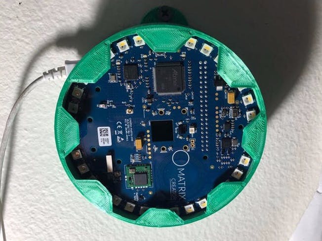
7. Printing & Assembling the CaseWe designed a case to replace the wall thermostat with the MATRIX Creator + Raspberry Pi assembly. If you would like to print a similar case, find the STL files attached here.
The back piece of the case has a hole for all the wires to go through. The back piece is secured to the front piece through a pressure fit. Both pieces have holes to screw the piece onto the wall.
And there you have it! Your custom thermostat complete with an enclosure and ready to be controlled using voice commands.
Enjoy the laziness.


Comments
Please log in or sign up to comment.