Arduino Pro Mini 5V 16MHz
SD card module
RTC module with battery
RJ11 socket (optional)
BMP180 pressure sensor (preferably with a 5V input power option on a breakout board)
SHT31-D humidity sensor
24 X 4 LCD module with I2C interface
3 small push buttons
Lots of little wires
Soldering iron
and also a usb to serial adaptor to program the arduino.
Why I Made ItI wanted to be able to view live atmospheric information and also log it for looking at it in a graph whenever I want. Simply
I have not included a case in this project as I'm sure people will know what the best case for them selves is.
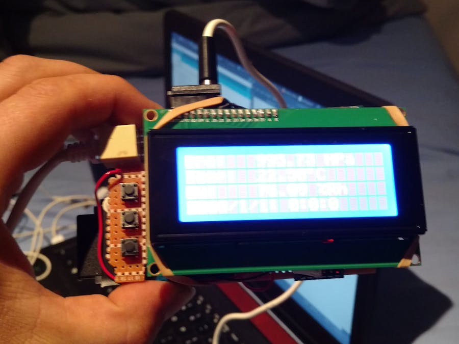
I started by soldering all the components onto a strip board like so I thought we be most efficient.
The screen just plugs straight into that little header you see on the top between the rj11 plastic socket and the clock battery.
Then proceeded to cut the strips so that the components are not shorted out like so:
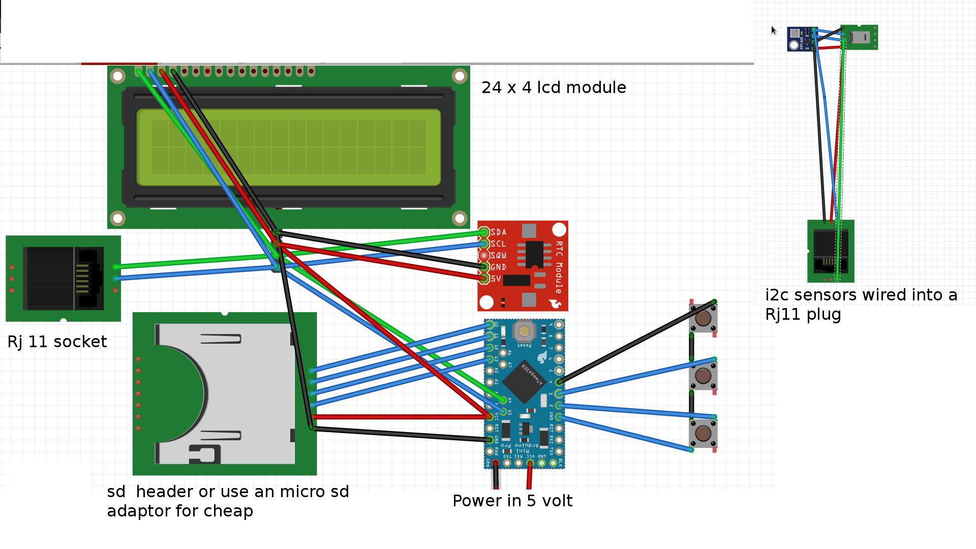
I then soldered on wires to join the components to the necessary point on the Arduino.
Pin numberPin numbers:
10 -- to sd card ss or some people say cs
11 -- to sd card mosi
12 -- to sdcard miso
13 to sdcard sck
Pin numberPin numbers:
A5 -- to i2c strips that connect to the header for screen A5 is SCL
A4 --- to i2c strips that connect to the header for screen A4 is SCL
It makes sense when you look at the pins at the back of the screen which way round they go.
sda to sda.
scl to scl
Then connect positive +ve and negitive -ve to the header to power all the sensors and devices. then wire all all sda to the same strip wires are needed as the clock does not line up with the other two devices.
Wire in the optional rj11 connector if you want to be able to remove your sensors or not if you dont mind just solder then directly in.
Pin numbers:
2 to button 1
3 to button 2
4 to button 3
Ground to the other contact of all the buttons ( I just had one wire and joined all the button pint on the negative side to one rail.
I have my sensors on the end of a lead in a plastic tube with a hole in it.
for the power supply I used an old connector I had lying around. there are many different power plug options I assume people will chose their own preference.
The buttons are to set the time. for the clock
The way the program works is if you have the bottom button of the three pressed down when you switch the thing on it enters a clock set mode and you use the top two buttons to change the value. Top for + 1. Middle for - 1. and bottom to set the next bit of the clock. The menu goes, set year. then set month. and so on until minutes.
The logger logs the data in a file on the sd card called DATALOG.txt and it is in csv format.
It's quite low power and last 4 days on a 2000 Milli amp hour lithium power pack sometimes the pack will cut out if the logger doesn't draw enough power. i found that lithium power packs usually have a led you can switch on as a torch on the if you do that it doesn't switch off anymore.
i added a 50 k ohm potentiometer to the screen back light contacts and it works very well as a brightness knob.
Here is a small example of the output file format:
2018/10/14: 1:23:0,997.31,19.10,78.56
2018/10/14: 1:24:0,997.42,19.10,78.55
2018/10/14: 1:25:0,997.47,19.10,78.54
2018/10/14: 1:26:0,997.44,19.09,78.59
2018/10/14: 1:27:0,997.55,19.09,78.59
2018/10/14: 1:28:0,997.47,19.10,78.60


Comments
Please log in or sign up to comment.