


Hardware components | ||||||
_ztBMuBhMHo.jpg?auto=compress%2Cformat&w=48&h=48&fit=fill&bg=ffffff) |
| × | 1 | |||
 |
| × | 1 | |||
 |
| × | 1 | |||
 |
| × | 1 | |||
| × | 1 | ||||
| × | 1 | ||||
First things first. Start by 3D printing the pan-tilt frame (by Miguel Álvarez). It is a simple design which consists of a base, a gimbal, and a camera support with a camera adjusting part. I have used 22m of PLA in a Da Vinci Jr. The result is as shown below.
Mechanically the device is very simple. The micro-servo controls vertical rotation (tilt), while the stander servo controls horizontal rotation (pan). The GoPro camera is made firm with a velcro. The base includes 4 holes for attaching the device to any other structure.
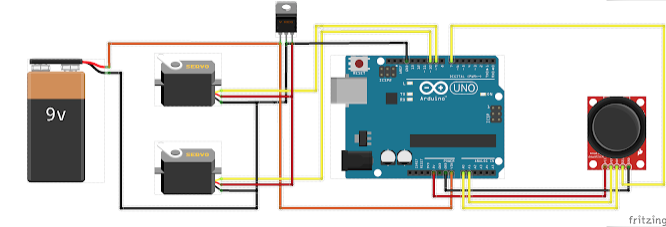
Let's go for movement. The main idea is using an analog two-axis joystick, similar to those of game consoles. This joystick is attached to the Arduino, which is in charge of reading the joystick axis positions and sending the necessary signal to the servos. A Fritzing diagram is included in the attachments section.
A delicate question is powering up the servos, which demand for 5-6V, and a consumption high enough for the Arduino 5V output. In order to deal with this, a voltage regulator is needed, in this case a LM7805 (any other 5-6V voltage regulator capable of 0.5A minimus might be used). If you want a faster Turing rate of the servos, you might replace it by a LM70806.
The main power could be anything that supplies a minimum of 7V. In this case we propose the use of a 9V battery.
PROGRAMMINGOk, everything is ready for using. Let's program the Arduino. The program is very simple. In the setup () function we initialize the serial port (mainly for debugging purposes), the digital input and output ports, and calibrate the average value of the joystick axis values at rest. This last part is important for calculating the servo movement. Last, the place the servos in their initial positions.
In the loop () function we read the joystick switch and the analog inputs. If we press the joystick switch the servos are commanded to their initial position. Otherwise, we change the servos positions by the sense and displaced amount of the two joystick axes.
The program is parameterized so that it is easy to change its operation. The conversion from joystick axis displacement to servo displacement is achieved by a proportional controller using the KP_AX and KP_AY constants. The larger these are, the greater will be the servo displacement.
adx = analogRead (PIN_AX);Last, in order to smooth the servo movement two variables are used. On the one hand, those that serve as set-points for the desired angles (variables trg_pan and trg_tilt). On the other hand, those that store the actual positions of the servos (variables pos_pan and pos_tilt). Again, a proportional controller is used with the KP_PAN and KP_TILT constants. The larger these are, the faster the movement is.
ady = analogRead (PIN_AY);
deltax = ((float) adx - centerx) * KP_AX / 512.0;
deltay = ((float) ady - centery) * KP_AY / 512.0;pos_pan += (trg_pan - pos_pan) * KP_PAN;
pos_tilt += (trg_tilt - pos_tilt) * KP_TILT;
servo_tilt.write (pos_tilt);
servo_pan.write (pos_pan);
One the circuit is powered up, the servos turn to their initial positions. If we move any axis of the joystick, the corresponding servo will move in the same direction. If we release the joystick axis, the servo will stay on position. Once the servos get to their limits, the software will not force them. If at any time the joystick switch is pressed, the servos will turn to their original positions. You can see the system working in the next video.


Comments