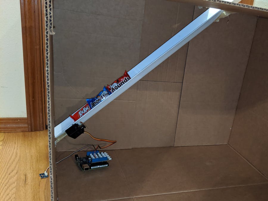
This is a design for a touchless candy dispenser based on the Intel(R) Cyclone(R) 10 LP FPGA Development Kit [1]. It uses a photoresistor connected to a digital input pin on the FPGA to detect when someone places their hand beneath a chute. It then activates a PWM-controlled servo to dispense a candy (or maybe more or fewer than one if the mechanical design is less than ideal, as was the case for my prototype ;-) ).
#IAmIntel
Mechanical designThe overall design is to place an angled chute for candy to slide down in a box with an opening at the bottom of the chute for the candy to exit the box.
A wire nut is positioned in the corner of the chute close to the opening, with the open end of the nut facing up, so that a row of candies can rest against it.
The servo is attached beneath the chute, and a slot is cut in the chute so that the servo arm can rotate into it and lift one end of the next candy above the wire nut. The candy then slides past the wire nut, out the opening, and into the waiting hand. Rigid tape folded over the servo arm helps to push the candy high enough to clear the wire nut.
The photoresistor is threaded through a slot beneath the opening for the chute:
See the picture below for the jumper connections and where to attach the 4-pin cable for the light sensor. Pay careful attention to orient the servo connector such that the ordering of the cable colors matches what is shown in the diagram.
IMPORTANT: Set the voltage selector switch on the base shield to the 3.3V setting, since the IO pins on the development kit are not 5V-tolerant.
The compilation step only needs to be performed once.
- Clone the repository listed in the project info.
- Open the Intel(R) Quartus(R) Prime Lite Edition software.
- Click the "New Project Wizard" button.
- Click the "Next >" button.
- Select the cloned repository directory as the working directory.
- Enter "candy-dispenser-c10lp" as the project name.
- Enter "candy_dispenser_c10lp" as the top-level design entity name.
- Click the "Next >" button.
- Click the "Next >" button on the "Project Type" dialog to accept the "Empty project" default.
- Click the "Add All" button in the "Add Files" dialog.
- Click the "Next >" button.
- Select the "Cyclone 10 LP" device family.
- Select the "10CL025YU256I7G" device.
- Click the "Next >" button.
- Click the "Finish" button on the "EDA Tool Settings" dialog.
- Press Ctrl+Shift+A to open the pin-assignment editor.
- Enter the following pin assignments, specifying "Location" as the assignment name for each:
- value PIN_L14 to led
- value PIN_G2 to servo
- value PIN_F3 to pr0
- value PIN_E1 to clk_50M
- Press Ctrl+S to save the pin assignments.
- Press "Ctrl+L" to launch the compilation.
- Wait for compilation to complete.
The programming step needs to be performed each time power is connected to the FPGA.
- Attach the 5V power supply to the FPGA development kit. The servo draws a substantial amount of current, so powering it via USB is inadequate.
- Connect the black USB plug of the programmer cable included with the development kit to the computer running the Intel(R) Quartus(R) software
- Click the "Programmer" button in the toolbar (looks like a diamond with multi-colored diagonal lines piercing its center).
- Click the "Hardware Setup..." button.
- Click the dropdown for "Currently selected hardware:".
- Select "Cyclone 10 LP Evaluation Kit".
- Click the "Close" button.
- Click the "Auto Detect" button. Choose to overwrite the existing settings, since it will detect an additional device. It will prompt for the type of device. Select "10CL025Y" from the listed options.
- Select the 10CL025Y device and then click the "Change File..." button.
- Choose the "output_files/candy_dispenser_c10lp.sof" file.
- Check the "Program/Configure" checkbox.
- Click the "Start" button.
- Optional: Disconnect the USB programmer cable from the development kit.
- Place the dispenser such that light shines on the photoresistor.
- Place hand under chute, over photoresistor and wait for candy to dispense!
The photoresistor could be connected to the ADC input on the development board to make the light threshold for activating the servo configurable. I started developing a driver for the ADC in the adc branch of the repository, but it doesn't work yet.


Comments
Please log in or sign up to comment.