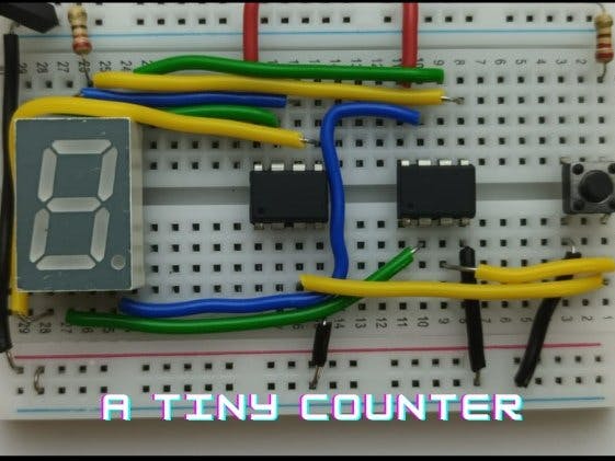
We are from the Electronics club, Center For Innovation, IIT Madras and we are presenting our blog page. Let's get started with our first blog post on making a simple counter using an ATtiny microcontroller.
OverviewIn this project, we will be controlling the 7-segment display using 2-ATtiny microcontrollers which get input from the push button and increment the number. The ATtiny will be programmed using an Arduino Uno through ISP mode. Now let's get into the project.
ComponentsLet's begin with taking a look at the individual components used in the project.
ATtiny:
ATtiny (also known as TinyAVR) is a subfamily of the popular 8-bit AVR microcontrollers, which typically has fewer features, fewer I/O pins, and less memory than other AVR series chips. ATtiny85 is an 8-pin – 8bit AVR – RISC microcontroller that has a single bi-directional IO port ( Port B with 6 pins; PB0 to PB5), a 10-bit analog-to-digital converter, fully functioning 4 wire SPI, and two 8-bit timers. It has :
- Flash memory of 8Kb to store programs.
- EEPROM memory of 512 bytes to store the data.
- SRAM of 512 bytes can be used during program execution and temporary data storage. 32 GPR (general purpose registers) are attributed to serving the purpose.
ATtiny PINOUTS:
- RESET: An active low pulse is applied to this pin to reset the microcontroller
- Vcc: This pin is connected with a 5 V supply.
- SCL: For interfacing to provide a clock signal.
- MISO: Used as Master In Slave Output pin in SPI communication.
- MOSI: Used as Master Out Slave In pin in SPI communication.
- GND: This pin is connected to the circuit ground.
- SDA: For interfacing for sending and receiving data
A 7-segment display is an electronic display device that is used to display numerical. The seven LED segments of the display and their pins are “a”, “b”, “c”, “d”, “e”, “f”, and “g” as shown in the figure given below. Each of the pins will illuminate the specific segment only. Power (or voltage) at different pins can be applied at the same time, so we can form combinations of display numerical from 0 to 9. Each display unit usually has a dot point (DP), which could be located either towards the left or towards the right of the display pattern.
Types of Seven Segment Display:
- Common Cathode - Here, all the cathode pins are connected to the ground or logic 0. The other anode pin is taken out and is given to high or logic 1 signal to illuminate the particular led segment from “a” to “g”
- Common Anode - Here, all the anode pins are connected to a high pin or logic 1. The other cathode pin is taken out and is given to ground or logic 0 signal to illuminate the particular led segment from “a” to “g”.
In a common cathode, all the cathode pins of seven LEDs are connected, whereas in a common anode all the anode pins are connected. We will be using a common anode display.
Truthtable for displaying Decimal numbers
Step - 1:Set the Arduino Uno Into ISP Mode.
Since we want the Arduino to program the ATtiny85 from the Arduino IDE which requires burning the bootloader to the ATtiny85 we will need to "prep" the Arduino first by uploading the ISP sketch to it.
ISP MODE:
In-system programming (ISP) is the ability of some programmable logic devices, microcontrollers, and other embedded devices to be programmed while installed in a complete system, rather than requiring the chip to be programmed prior to installing it into the system.
In the Arduino IDE select File, Examples, and there Arduino ISP has to be selected. Now open and upload the ISP sketch to your Arduino Uno.
Step - 2: Connecting the Arduino to the ATtiny pins
Make the following connections.
connect the capacitor negative pin to GND and the other pin to RESET.
Step - 3: Add Support for the ATtiny85 to the Arduino URL Board Manager:
In Arduino, go to File—> preferences—> Additional Boards Manager URL
Paste the following link
https://raw.githubusercontent.com/damellis/attiny/ide-1.6.x-boards-manager/package_damellis_attiny_index.jsonStep - 4: Install the ATtiny Board Package
- From the Arduino IDE, go to Tools.
- Then go to Board and then Boards Manager which when clicked a new tab will show up and at the top of the tab type: ATtiny.
- Now, select and Install the ATtiny by David. A Mellis.
- Now, go to Tools and then go to Board, and finally select Attiny85.
Step - 5: Making the ATtiny85 Arduino compatible
Quick checklist before pressing "burn bootloader"
Go to Tools and then Board, where you would have to scroll to the bottom and select ATtiny85. Under Tools, go to Processor and select 8 MHz (internal). Again, go back to Tools, then to Programmer, and choose Arduino as ISP. Check that all wiring, capacitor, and board selections are correct. Finally select Burn Bootloader. Leave the wires connected and a message will appear saying "Done Burning Bootloader"
Step 6:
- Since the 7-segment display has 10 pins and we’ll be using 7 pins we need 7 output pins. But we just have less than 5 output pins so we’ll be using 2 ATtiny ICs.
- 4 of the LEDs, of the 7 segment displays will be controlled by IC-1
- Now, the rest 3 will be controlled by IC-2
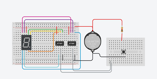
- The assembly of the ICs are in the schematics.
- The input is taken from a push button and given to both ICs so that both ICs remain synchronized.
int m = 0;//here m is defined as a counter
int LEDs[] = {0,1,2,3};//the outpins of the attiny
The LEDs array contains the pins of the ATtiny chip.
From the above diagram, we can write down the LEDs which are off as 1 (as we are using common cathode mode)
Say for example: for 1 {1, 0, 0, 1, 1, 1, 1}
Divide the 7 elements into the first 4 and the last 3
{1, 0, 0, 1}, {1, 1, 1}
The first array is sent to 1st ATtiny and the second array is sent to 2nd ATtiny
The process is made for other numbers and stored in the corresponding array
0 sets the pin to low and allows current to pass through and setting 1 stops all current from flowing through.
void setup() {
for (int i = 0; i<3; i++) pinMode(LEDs[i], OUTPUT);
pinMode(4,INPUT_PULLUP);
For loop initializes all the specified pins as output
void a()
{
for (int i = 0; i<3; i++) digitalWrite(LEDs[i], one[i]);
} //continue the process for b,c,d… functions
...
void j()
{
for (int i = 0; i<3; i++) digitalWrite(LEDs[i], zero[i]);
}
Each function varying from a to j executes the specific lighting order needed to display the number on the seven-segment display.
for(int i=0;i<3;i++) digitalWrite(LEDs[i],zero[i]);The for loop executes the digitalWrite() function for i= 0, 1, 2 and sets the led with respect to the right LED configuration needed to display the pattern
VOID LOOP Function:
if(digitalRead(4)==LOW)
{
while(digitalRead(4)==LOW){}
m=m+1;
}
if(m==1){
a();
}#continue  for other values of m
...
if(m==0){
j();
}
m=m%10
If the button is pressed, the ground and PIN 4 get connected, send a low signal to PIN 4, and wait till the button is released. After the button is released, a variable m value is increased by 1
The value m increases by one whenever the button is pressed and gets reset if the value of m reaches 10. The value of m is the value printed on the 7-segment display.
Working:Hope you find our work interesting. Stay tuned for more blogs...


_ztBMuBhMHo.jpg?auto=compress%2Cformat&w=48&h=48&fit=fill&bg=ffffff)


_3u05Tpwasz.png?auto=compress%2Cformat&w=40&h=40&fit=fillmax&bg=fff&dpr=2)
Comments
Please log in or sign up to comment.