


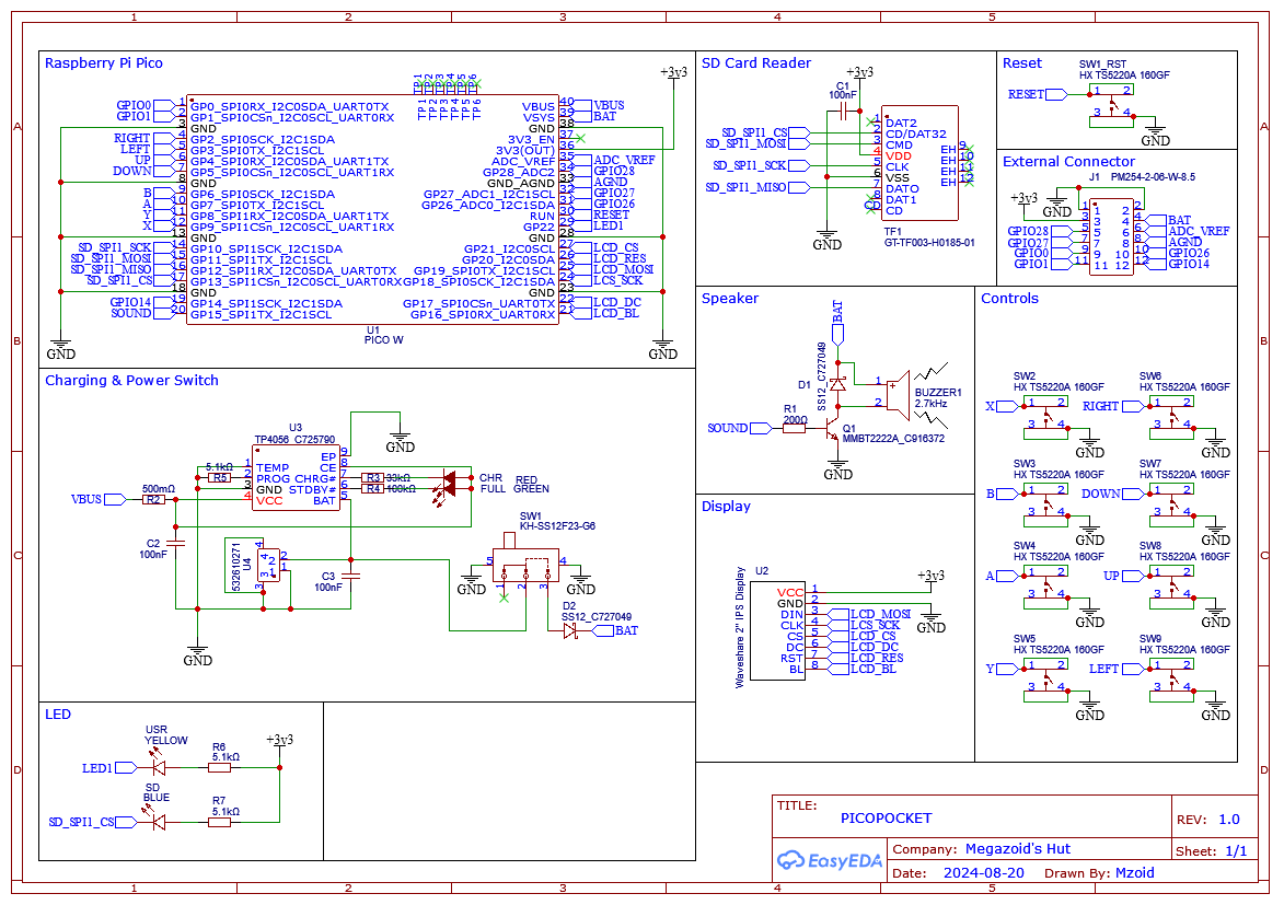
PicoPocket is a handheld device that works on either the Raspberry Pi Pico (RP2040) or Raspberry Pi Pico 2 (RP2350). It's based on the Picopad schematic, and operates on the PicoLibSDK by Miroslav Nemecek.
Before diving in, take a look at the bill of materials and asks yourself if you really want to get involved? You need to be adept at 3d printing and finishing, and soldering 0603 sized SMD components. If all of this looks like a doddle - crack on.
My PCB Gerber files and STL's are Public Domain. Everything else is whatever Licenses that other people assigned to their work. I take no responsibly for anything. I am not linked in any way with the open-source gaming console Picopad.
The image above is most of the parts. Missing from the image are the capacitors, resistors, diodes, LED's, NPN transistor, TP4056 & some 1.3mm clear grass trimmer line that I used as light pipes for the LED's.
The Waveshare display is kind of expensive. I used it because it's good quality and easy to source. If you use a different one, you will need to redesign the PCB & case. USB C Pi Pico's (Chinese clones) or standard Micro USB Pi Pico's.both work.
Since you know what you are doing, there isn't much to say about the soldering. I personally start on the battery side of the board first. The Schottky diodes need to be the right way around, as do the LED's. LEDS colours I use are red for CHR (charge), green for FULL, orange for SD, and yellow for USR (the user LED).
When attaching the Waveshare display, you need to first completely remove the rear PH2.0 8PIN interface. It is not needed. You then solder an 8 pin male header to the screen, and remove the plastic spacer. The screen needs to be 1mm from the PCB. I used some slightly thicker (1mm) foam double sided tape under the screen.
You will also have to enlarger the upper right screen hole (see image 2 above). I drill mine out with a Dremel drill. I messed up the screw alignment slightly... oops
Attach the speaker with hot-glue, and the battery with a bit of double sided tape.
I've used eSUN Bone White PLA+ filament for the main body of the case. Other colours used were black, grey, yellow, orange red & brown PLA from Eryone. The case was printed on a Bambu Lab A1 mini 3D Printer.
The Base
The base is printed in what you might describe as the "correct" way. I used a wide 8mm brim to stop corner lift. The other setting changes are :
- System preset = 0.16mm Optimal
- Brim enabled - Outer brim only 10mm
- Supports enabled - Snug
- Bottom surface pattern Hilbert Curve
- Seam position = Back
You could also slow down the bottom layer print speed for a better finish. After printing the base, it's bottom curves can be sanded to a smooth finish using grits from 240 to 1500.
The Top
This is printed in the "wrong way"... why? Just accept it and move on. Mostly default setting, with the following changes:
- System preset = 0.16mm Optimal
- Brim enabled - Outer brim only 10mm
- Supports enabled - Default
- TOP surface pattern Hilbert Curve
You could also slow down the top layer print speed for a better finish. After printing the top, carefully remove the supports and brim. This takes a while to do well, as does the sanding of the base.
The Buttons and Thumbs stick
System preset 0.16mm Optimal, again with brims (8mm) and then sanded with grits from 240 to 1500. If you want it to feel like it was injection moulded, you have to put the work in.
Alternate Designs
Some alternate case designs are available on TinkerCad : LINK
To get 4 PLA colours on the speaker insert, you need to use the painting function in BambuStudio. A combination of triangle painting and the fill bucket and you can get the 4 PLA colors assigned to the insert. It takes some practice. When it's ready and AMS lite is all setup, you print with a 2mm brim. After printing, leave the brim on, and carefully superglue the insert into the case.
I glue light pipes for the LED's using 1.3mm clear lawn trimmer line. This generally goes wrong, and you have a whole bunch of sanding and buffing to make it look like you didn't get superglue everywhere. Good luck👍
I used some 0.5mm silicone sheet to dampen the button's clickiness. This doesn't have to be that accurate. Just cut some sheet as shown in the picture. Without it, the buttons are probably going to have too much rattle, although you could adjust them.
Due to some rushed design choices, the top 2 screws don't have very good anchor points. Basically, the case should hold together fine if you screw it together once and use some Loctite 243 on the top 2 screws. Nobody is getting this far, so who cares I guess ;D
Just download the SD card contents for Pi Pico 1 or 2 from PicoLibSDK by Miroslav Nemecek and put it on your SD card. You will figure it out. There are versions for the Pico 2 Arm & RISC-V modes.
You could of course make your own device using the Picopad Schematic like I did, or buy a Picopad or Picopad kit. It's a fun development platform that may get further updates that utilise the more powerful Pi Pico 2 in the future. Even as it stands, it has a lot of fun things for a non coder (like me) to mess around with. Many thanks to the software and hardware designers who worked on Picopad.


Comments
Please log in or sign up to comment.