After removing and replacing my 28C256 32KB EEPROM from the breadboard to reprogram it in the EPROM Programmer, the pins started to get a bit disgruntled.
Ideally I'd like to use a ZIF socket on the breadboard but also minimize the breadboard area it consumes. While 28 pin 0.6" sockets do exist, the 40 pin versions appear to be cheaper and more freely available. Aside from the space issue, most ZIF sockets today don't have breadboard friendly pins: too small or too short which makes for wobbly connections.
My solution looks like this:
As usual, I first try to find a solution using what I already have. Double-sided soldering on a protoboard while trying to maintain solder bridges turns out to be a task for smaller, younger hands so I gave up: all the soldering for the pins, including the bridges, needs to be done first since this work will be obstructed by the ZIF socket later. Tedious.
Many of the Makers I follow on YouTube make use of PCBWay and JCLPCB. I figured this was my opportunity to dip my toe in this game: simple project, what could go wrong? My choice of service was driven by the software: I downloaded several free products but EasyEDA stands out to me as truly being simple for novices to get going in. EasyEDA and JCLPCB go hand in glove so that's how I ended up choosing JCLPCB.
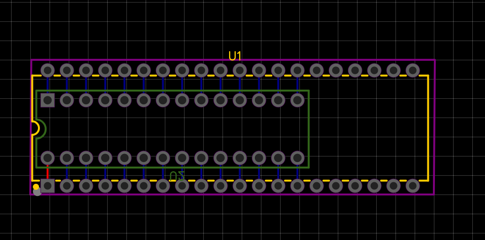
Most of these products want to start with a schematic and then do the PCB layout for you which didn't seem ideal for such a simple layout. The biggest challenge with this birdsnest was to avoid false connections where my conductors overlap. My trick for getting the pins on the underside of the board to line up perfectly with a breadboard was to "pretend" to use a 28 pin 0.3" DIP socket on the underside.
When you then tell EasyEDA to convert to a PCB, you need to reduce the footprint and move your sockets around. The first thing you do is move the 28 pin DIP to the other side of the board and then be sure to flip it around so that the two socket positioning notches line up.
Then you export the Gerber files which makes a ZIP for you to upload to JCLPCB (link below under "Custom parts and enclosures").
I designed my board the evening of July 20th and uploaded it to JCLPCB. They estimated 1-2 days to fabricate and 3-5 days for DHL to ship it to New Zealand. My order arrived at my door first thing in the morning on July 26th. Excellent service.
Since my board is so tiny, the minimum quantity was 5 (I have some spares now) and the price for all 5 boards was USD 2.
DHL Express Worldwide to New Zealand (the only choice offered to me) was about $20. And then JCLPCB threw in a $10 first time customer discount bringing the total order to about $12.
Of course they arrived with yet more discount coupons: $10 toward my next order, $8 if I follow JCLPCB on facebook.. how do they make a profit?
Solder the narrow side first. Also, easier to keep track if you do the board the "correct" way around: cut 2x 28 pin strips and solder them into the outline of the narrow 28 PIN DIP socket (that doesn't exist). Use a breadboard as a jig to line up the pins and make it easier to get them square.
After soldering, I clipped off the excess length off the pins to make sure my ZIF socket would sit more flush over them.
Remove from the breadboard, place the ZIF socket, turn it over and finish the job.
My 28 pin ZIF socket finally arrived. A quick trim of one of my spare boards with the Dremel and I now have a more compact version that doesn't hang off the edge of the breadboard.


Comments
Please log in or sign up to comment.