


Hardware components | ||||||
_ztBMuBhMHo.jpg?auto=compress%2Cformat&w=48&h=48&fit=fill&bg=ffffff) |
| × | 1 | |||
| × | 1 | ||||
 |
| × | 1 | |||
Software apps and online services | ||||||
 |
| |||||
These LCDs are so common and have been around for so long that simple reliable drivers for them should be a solved problem. It isn't.
For example, inserting delays into your driver to wait for the LCD to finish an instruction is just hinky when the device comes with a perfectly reliable interface to ask it if it is still busy or not.
My end goal is a stable, clean and simple driver in Z80 assembler but it is just so much easier to prototype the LCD communication in the comfort of Arduino-land.
The DeliverableI've arrived at a point where I have a super stable implementation in Arduino-land. The code is deliberately verbose with the intent that it should be obvious to see what it does and cut-and-paste it into your own solution. Even so, the whole things is still only ~350 lines long.
CreditsA while back I built Ben Eater's 6502 breadboard computer and he has a great video series where he works incrementally through building a driver for these LCDs in 6502 assembler. This is where I first saw the folly of peppering the code with delays rather than just reading the LCDs busy flag.
When searching for some C source in Arduino-land that was reasonably small and consumable, I strayed into Hans-Christoph Steiner's driver from back in 2010. What my code ended up being is a variation on this but without all the "delayMicroseconds(..)" calls which I replaced by reading the LCD busy flag.
Limitations- There is no avoiding inserting delays in the initialization process for either 8 or 4 bit mode. The flow charts in figures 23 and 24 of the Hitachi data sheet are explicit about this (their initialization sequence, in a nutshell, is: "beat it with a rock")
- Initialization for cold boot (initial power up) for both 8 and 4 bit mode are super stable. A warm boot when in 4 bit mode is a bit dodgy. I have yet to get this 100% stable (open to ideas..)
These devices date back to long before the big flood in the Old Testament. At that point they had the foresight to offer a 1 line and a 2 line mode in the interface. More than 2 lines was obviously not a thing they had in mind.
This has resulted in quite peculiar internal addressing for the consecutive lines in the more "recent" models (like the 20x4 LCD).
Another issue I have with most existing implementations is the idea of clearing the screen and then just writing characters and letting them flow. Because of the peculiar line addresses, text will not simply flow from line to line in the 4 line LCDs. Also, when you run off the end of the last line of the LCD (any model), it has this nifty "feature" of wrapping back around to the start.
I far prefer absolute addressing:
- no scrolling
- no assumptions about where I want to go on wrap or overflow
Make it the developer's problem to ask how many rows there are, how many columns there are, and then write characters to specific coordinates. Yes, I still have a simple API to write a single character to the next position but:
- it works correctly when it comes to the end of one line and the start of the next
- if you write off the end of the LCD, no wrap: your characters just go in the bin
I used another "read" function of the LCD's to ask it what the current position was after each character write and this allowed me to reverse engineer the start position of each row in the 20x4. I left that code around so it can be used to figure out positions on some future model again if needed.
My public API is:
LCDInitialize();
//
// coordinates are 0-basedLCDSetCursorPosition(byte col, byte row);
//
// write a character in the current pos, then increment posLCDCharacter(char c);
//
// same as calling both of previous 2 but in 1 stepLCDCharacter(char c, byte col, byte row);
I should probably add a clear screen API. Easy to cut and paste it from LCDInitialize: simply the last 2 lines on that function.
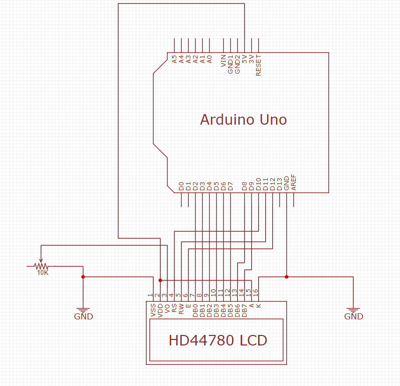
How It WorksI won't discuss the wiring for the contrast potentiometer (V0) or the backlight (A and K). There's not much mystery in those. I'll discuss the part that took me a while to trawl through and figure out:
The device interface consists of 2 "registers":
- instruction register
- data register
The sole function of the RS pin is to select between the instruction register or the data register: low for instruction register, high for data register.
Instruction register is mostly written in my driver. Data register can be read and written. We write data to display a character or set the address (cursor position). We read data to get the busy flag or the current address (cursor position). The RW pin is used to distinguish between these reads (high) and these writes (low). So, stating the obvious, for instructions the RW pin is mostly low (with the exception of reading the Busy flag).
That leaves the EN (Enable) pin: this is essentially the clock signal for communicating with the LCD. Normally you have this line low and then to send a clock pulse you cycle it from low to high and then back to low again.
What this does is tells the LCD: "I'm done setting up what I want on pins D0..D7, please go ahead and execute". Writing is the easy version. Reading is a little less obvious:
In this case it is the device's responsibility to set the values on pins D0..D7 and it does this during the clock pulse. I've found that you need to read these lines while the EN line is still high. Once it goes low, they are no longer stable.
I've illustrated using the 8 bit operations : they are simpler. But the 4 bit operations are just the same thing twice in each case.
Too Much InformationThere are 9 instruction register instructions. My descriptions are abbreviated. I've attached the Hitachi datasheet for more detail.
Clear Display: clears display and sets address 0 in address counter.
Return Home: sets address 0 in address counter.
Entry Mode: sets left-to-right or right-to left incrementing of the address
Display On/Off: you guessed it, also hide/show cursor, cursor blink on/off
Cursor/Display Shift: essentially scrolling : not useful to me
Function Set: initialization of 4/8 bit interface, # of lines, font size
CGRAM Address: set Character Generator address (for making own fonts)
DDRAM Address: can be used to set current address ("Display Data")
Read Busy Flag and Address: check the busy flag and get last address
There are 2 data register instructions (overuse of the word "instruction"?!)
Write Data to CGRAM or DDRAM: uses address set above, increments after write
Read Data to CGRAM or DDRAM: uses address set above, increments after read
My driver only makes use of:
Function Set - initialization
Display On/Off - initialization
Cursor/Display Shift - initialization (just to turn it off)
Clear Display - initialization (should be its own API)
Read Busy Flagand Address - to wait for LCD to finish current operation
DDRAM Address - to set cursor position
Write Data to CGRAM or DDRAM - to write a character
ConfigurationThere's a fundamental difference between the 8 and the 4 bit interface. The 4 bit interface has merit if you are low on GPIO pins. To switch between these two I have a preprocessor define at the top of the code (LCD_8_BITS). Comment it out for the 4 bit version.
Note: the 4 bit interface uses pins D4..D7, not D0..D3 on the device.
I have some global variables that need to be manually configured in LCDInitialize() but at least that's only one place in the code. I have the settings for my 16x2 and my 20x4. Share any others with me as added and I'll update the code and this image.
I chose the Uno because it is so common and because it doesn't have the limited number of GPIO pins as my usual favourite (the Lolin D1 Mini from Wemos).
I don't use the Uno much but Port D's pins are in a nice little 0..7 set that works so cleanly with an 8 bit ribbon cable to connect the data lines directly across to the LCD.
The meaning of the TX and RX were lost on me until I started attempting to upload code while the LCD was on. These two pins are shared by the serial connection which makes them useless for anything else in a development scenario.
I was already on a roll though so I just shifted across 2 pins. This may explain my peculiar pin choices and verbose code (digitalRead / digitalWrite rather than direct port access using PORTB and PINB).
Next Steps..Moving on to the Z80 version..


Comments
Please log in or sign up to comment.