Ben Eater has a series of 3 videos that start with a detailed breakdown of the PS/2 interface and end with actually hooking up and using a keyboard with his computer design:
- PS/2 keyboard research episode
- PS/2 keyboard interface hardware episode
- PS/2 keyboard 6502 assembler software
If you have not already, I recommend watching his series (and why not buy his kit too?).
I want to actually use the keyboard in my own 65C02 computer and the problem I had was that Ben's design wasn't working reliably for me: the key codes were unreliable, especially when running at 4Mhz.
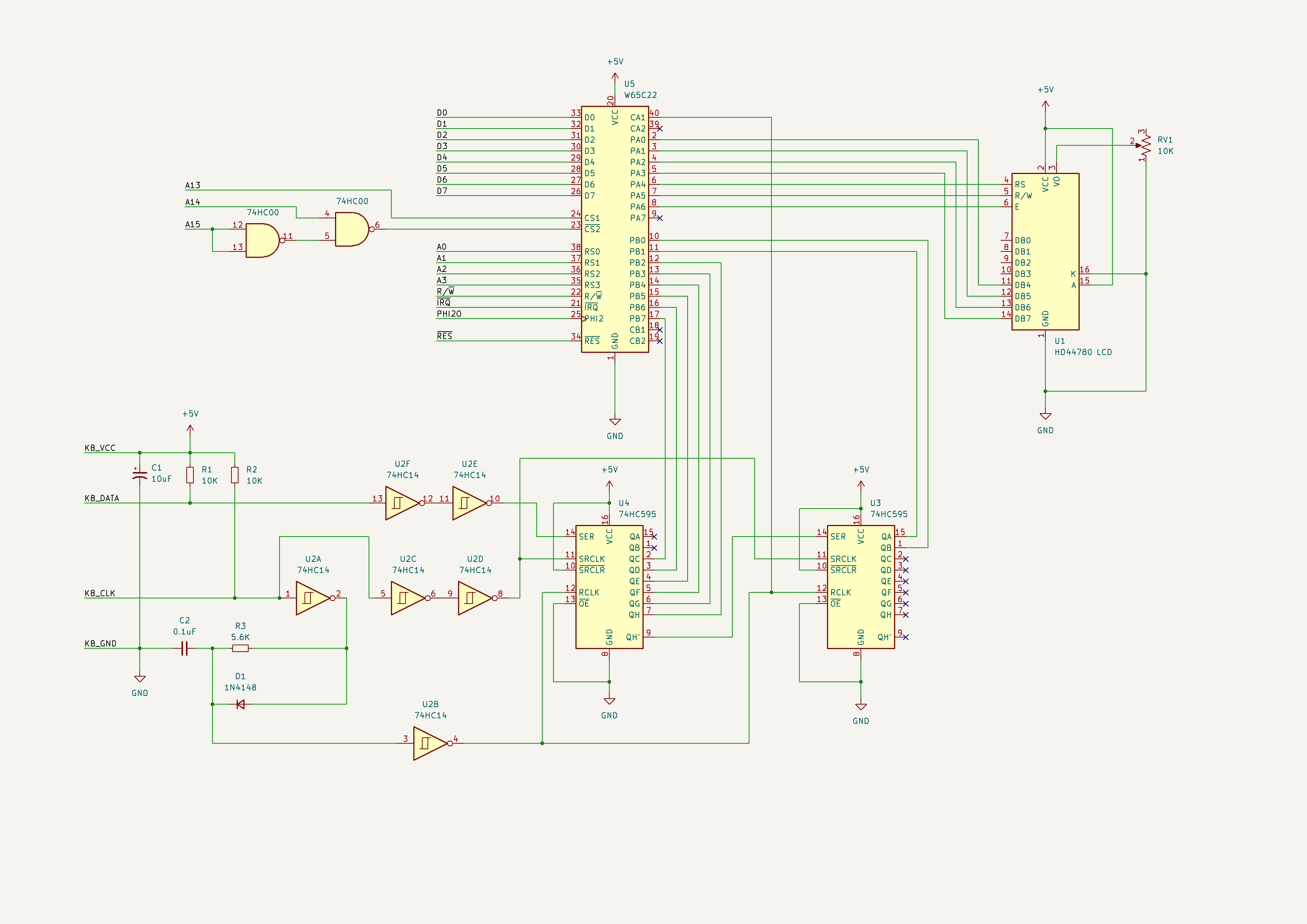
Also, Ben glosses over switching the LCD from 8 bit to 4 bit mode to make room on the 6522 and never really documents the keyboard schematic (the keyboard interface is not part of his kit so it is not included in the overall schematic).
I also have prior experience working with 20x4 LCDs (rather than 16x2) and I needed to upgrade that part of the software anyway (see my 20x4 driver project).
Note: while the keyboard shown here may look like a RC2014 keyboard, which it is, I've modified it (read more about that project) so that it behaves like a PS/2 keyboard (it works, via PS/2 to USB adapter, when plugged into a modern PC).
CreditsAs a starting point for the keyboard schematic, I found a (flawed) version on reddit.com (credit to MicroHobbiest). Biggest thing missing was not showing where KB_INT connects through to CA1 on the 65C22.
For the LCD, there is a post on Ben Eater's Patreon which describes the changes to switch from 8 bit to 4 bit interface.
In my quest for stability I ran into some other posts online which I also took to heart. For example:
- 10K pullup resistors on the clock and data lines from the keyboard
- 10uF capacitor on the keyboard power lines
Ben's inspired idea of using the multiple clock pulses per key code to create a single 'interrupt' pulse is great. However, the pulse length with the R and C values from Ben's version (33K and 0.1uF) didn't work for me. Could this be because the clock frequency of the PS/2 varies by keyboard (between 10kHz and 16.7kHz or a period of 60-100us)?
I took this as my opportunity to learn more about how to use my oscilloscope and figured out that the ideal R value for my keyboards (both of them) is 5.6K.
I still did not get reliable key codes so my next step was to refactor the keyboard interface software to spend as little time as possible within the ISR (interrupt service routine). Instead of decoding PS/2 key codes to ASCII and keeping track of <shift> and <ctrl> in the ISR, I simply pushed the raw key codes into the circular buffer instead and decoded them in APIs called from the main program when fetching available keys.
I improved the code to be more reliable with regard to <shift> key states and added <ctrl> key states since my RC2014 derived keyboard requires the 2nd modifier key to get enough keys out of this tiny layout:
This still wasn't enough so I looked for a pattern in the errors. It seemed like the incorrect codes were always off by bit 0 or bit 1. On closer inspection with the oscilloscope both the data and clock pulses looked quite noisy, especially near the start of the key code.
My solution is to feed both KB_DATA and KB_CLK through two Schmitt inverters (the 74HC14 had 4 unused inverters just asking to be used like this). At such low speeds (between 10kHz and 16.7kHz) the additional propagation delay has no effect but the pulses are now super clean and the resulting key codes are now reliable.
My computer now has a working reliable PS/2 keyboard! I've been moving the parts from breadboard to perfboard. The image below shows successful EEPPROM and SRAM daughterboards in the background. Next step is to move the keyboard and LCD interface circuitry to a daughterboard and then create a motherboard for the 65C02 (and support circuitry).
Finally, it needs to have an RS232 daughterboard (ACIA and MAX232 as per Ben's design).
Included below is the schmatic with my differences highlighted. The high resolution version is also attached to this project.
I show the chip select for the 65C22 as per Ben's design (using A13, A14 and A15) but that could obviously be any address as required.


_4YUDWziWQ8.png?auto=compress%2Cformat&w=48&h=48&fit=fill&bg=ffffff)


_Ujn5WoVOOu.png?auto=compress%2Cformat&w=40&h=40&fit=fillmax&bg=fff&dpr=2)


Comments
Please log in or sign up to comment.