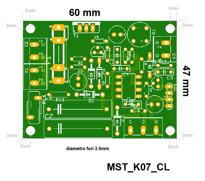
The motor regulator featured in this article is designed for universal brushed motors operating at 220V. It enables precise control over the motor's torque and maintains a steady rotational speed, regardless of load variations. This regulator is specifically tailored for use with washing machine motors that come equipped with a tachometer (or speed sensor), such as the MCA 30/64 motor. The model name of this regulator is MST_K07_CL.
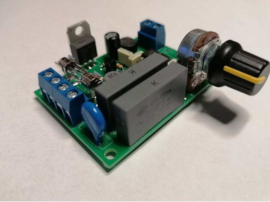
Figure below shows the photo of the assembled version.
The MST_K07_CL regulator implements the automatic torque control: the current of the motor is adjusted so that the rotation speed remains constant at the set value as the load varies. If the load, applied to the motor, tends to reduce / increase the rpm then the regulator will react by bringing the rpm value back to the set one. This type of regulation is obtained by means of the closed loop control that the regulator implements on the motor. This control is based on the electrical signal from the speed sensor which converts the rotation of the motor shaft into a proportional electrical voltage. As a reference we take the motors for washing machines (such as the MCA 30/64) in which there is a tacho sensor, coaxial to the motor, which supplies an alternating voltage of amplitude proportional to the rotation speed of the motor shaft. The MST_K07_CL regulator, suitable for these types of motor, reads this voltage and compares it with a voltage, set via a potentiometer, which represents the setting of the rotation speed value to be adjusted. The regulator will then power the motor so that the voltage value coming from the sensor, suitably conditioned, remains equal to the voltage value set by the potentiometer. To do this, the MST_K07_CL regulator uses an 8-bit microcontroller, in which a firmware that implements a digital PID regulator is loaded. The digital PID regulators then compare the digital signals that represent the inputs (reference and feedback) and generate an output signal which is the input of the power actuator. Specifically, the actuator stage consists of the TRIAC piloted with the ignition angle variation technique. In general, a TRIAC at zero crossing of the voltage present at its A1 and A2 anodes switches off and on again when a current pulse is present on the GATE terminal. By changing the instant of time in which the pulse is given on the GATE terminal with respect to the previous zero crossing (it is said that the phase angle is changed) the average voltage that powers the load is varied as only a portion of the half-wave of voltage is supplied to the load. So if you choose a zero ignition time (0 °) the whole half-wave goes to the load and in this case you have the maximum power supply and therefore the maximum motor speed. If you choose a time equal to half of the half wave (90 °) only half of the sine wave will go to the load and you have a regulation of 50%. Finally, if the TRIAC is turned on a few moments before the next zero crossing (180 °), no voltage will go to the load and there is a regulation of 0%.
The circuit of the MST_K07_CL works at the internal voltage of 5V obtained from the AC mains voltage through a transformless circuit.
MAIN FUNCTIONThe regulator implements some functions and protections:
SOFT START
The SOFT START function allows not to have sudden motor starts and consequent high current peaks. At start-up or from restarting from a STOP condition, the number of motor revolutions is brought progressively (following a linear ramp) from zero to the adjustment value set by the potentiometer. The soft start ramp time depends on the value set on the potentiometer at power on (or restart from STOP). If during the soft start ramp the adjustment value is changed then the soft start ramp will follow the new value: it continues if the new value is greater than the one previously set or ends if the new value is less than the current one. where the ramp is located.
START / STOP
The START / STOP auxiliary function can be inserted to activate / deactivate the motor connected to the regulator, without switching the regulator off / on or reducing the regulation to zero by acting on the potentiometer. This function therefore avoids on and off cycles of the regulator that stress the input stage or excessive use of the potentiometer. The function can be implemented simply by setting to zero, by means of a switch, the voltage that the potentiometer supplies to the regulator. In this case, (STOP) the regulator, seeing a regulation fixed at zero without the potentiometer being touched by its last setting, switches off the motor. Another advantage is that the restart from a STOP is done with the SOFT START. In the drawing the connections with which to realize the START / STOP function in the two application cases in which the potentiometer is soldered on the PCB or connected via a cable (as in the BOX version). In this case, a 4.7k resistor and a SPST (Single Pole Single Throw) switch must be used. It is understood that the STOP condition can also be activated with the potentiometer set to the minimum and that the START is activated just move from the minimum position of the potentiometer. This function can only be activated in controllers with firmware version 1.2 (in all controllers starting from 18/02/2021).
Connection diagram to realize the START STOP function in the cases of: Flying potentiometer and soldered on the PCB
In the case of a potentiometer soldered on PCB (right figure), it is advisable to intercept the point on which to solder the wire that goes to the switch (yellow in the picture) on the soldering side.
SAFE-START
The SAFE-START protection function has the purpose of avoiding unwanted motor activations when the regulator is powered by the user or after the reactivation of the electricity following an interruption. This protection implies that to start the regulator, after having powered on, you must always pass from the STOP condition, i.e. bring the potentiometer to minimum and then set the regulation or, if you use the switch to implement the START / STOP function., pass from the STOP position and then go to START without using the potentiometer.
MINIMUM and MAXIMUM ADJUSTMENT LEVEL
The minimum adjustment level is the minimum engine rpm value at which the governor brings the engine into control condition. This value depends on the circuitry that reads the information coming from the rpm sensor: the presence of offsets and voltage drops in this circuit leads to a minimum rpm value of 350 - 375 rpm
The maximum level of regulation is the maximum value of the motor revolutions at which the regulator brings the motor into control condition. This does not correspond to the typical maximum rotation value of the motor (from 12000 rpm to 16000 rpm depending on the model). For the values of the components that define it, the maximum adjustment level brings the engine to a number of revolutions of approximately 10000 rpm. It is possible to reduce this value (5000 rpm, 2500 rpm).
PROTECTIONSThe circuit of the MST_K07_CL regulator is equipped with the following protections:
- OLP ( Over Load Protection)
- RPM Sensor Disconnection
The OLP overload protection is implemented by the microcontroller that "senses" the overload condition. In the presence of an overload condition for a minimum time of 2s, the microcontroller switches off the TRIAC and puts the circuit in protection mode (TRIAC not activated). In this case, to reactivate the regulator, after having removed the overload condition, it is necessary to remove the power supply for a couple of seconds and then reactivate it.
The rpm sensor disconnection protection prevents the governor from rotating without control at maximum rpm due to breakage or electrical disconnection of the rpm sensor. As is well known, the regulator implements a closed loop control. If for some reason the feedback coming from the sensor is lost (due to disconnection or breakage of the sensor) the control loop is open and the information on which the regulator calculates the ignition of the TRIAC is missing. When this condition occurs, the regulator is put in the protection mode from which it is possible to exit only by switching it off and on again (after checking the electrical connection of the sensor or its integrity).
DESCRIPTION OF THE CONNECTORSThe electrical connections of the MST_K07_CL speed regulator must be made taking into account the function of the individual connectors as shown in the following photo.
electrical connections of the MST_K07_CL regulator in the standard version
The power connector (the one in blue with 4 places) must be connected to the mains voltage (220V) and to the motor. The speed sensor must be connected to the two-way blue connector. For this connection there is no polarity to respect when connecting the sensor wires because the signal coming from the sensor is of the alternating type.
The AUX connector
The AUX connector allows to interface the MST_K07_CL regulator to an external board which can be an Arduino or similar. This connector is present only in the digital version and can be used for the different operating modes of the regulator.
The use of the AUX connector allows you to use the regulator in different ways as you can:
read the motor rotation speed from the ROT pin;
read / force the speed setting or the voltage of the PWM pin;
force the internal voltage to 5V of the regulator from the outside through pins 5V and GND;
More information on how to connect the MST_K07_CL regulator to the washing machine motor (model 3064) is shown at the following link:
https://www.microst.it/Tutorial/mca3064b_6.html
MANUAL MODEIn this mode, the speed setting is always done manually by acting on the potentiometer. The configuration of the regulator is the standard one. The following picture shows the general diagram of the connections of the regulator to the motor for manual mode.
For the correct functioning of the regulator, the TRIAC must be equipped with a heatsink. A metal bar screwed to the TRIAC without insulation is enough because the metal tab of the TRIAC is factory insulated.
The following figures show the connections of the regulator to the washing machine motor (in our example the MCA3064).
Attention: The connector mapping changes from motor to motor.
Before making the connections, check the function of the individual wires arriving at the connector
This is the video of the regulator applied to the washing machine motor MCA3064. In the video you can see that the motor racts to the external torque to maintain constant the RPM


Comments
Please log in or sign up to comment.