


The project shown in this page is a circuit based on a relay that acts as a resettable fuse which allows to limit the current absorbed by a circuit to a threshold set by an external resistor: when the current exceeds the threshold value, the relay, that supplies the circuit, is opened by removing the power supply to the load. The fuse relay can be reset by a key who is in the board or can be exsternal connectedb by the SW connector
The assembled version of the Resettable electronic fuse
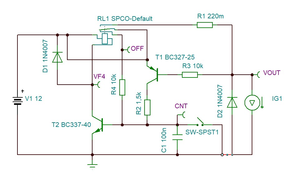
Description of the circuitThe circuit is very simple and it is based on a relay, two transistors, four resistors, one of which is a power resistor, two diodes and one capacitor.
Fig.2 : electrical schematic of the resettable electronic fuse
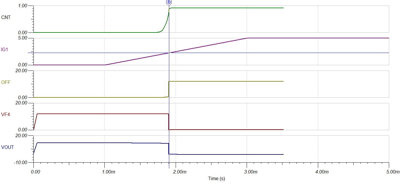
To measure the current supplied to the load by the fuse relay via the VOUT terminal, we measure the voltage drop that this current generates on the sensing power resistor R1. This voltage is used to turn on the PNP transistor T1. Under normal operating conditions, the output terminal VOUT is supplied as connected to the normally closed NC terminal of relay RL1 which is not energized. When the absorbed current generates a voltage on R1 enough to turn on T1, the base of the NPN transistor T2 is polarized by means of R2 and the relè is activated. In these conditions the VOUT node is not longer powered due to the fact that the relay is energized. Now the NO terminal is connected to the input voltage thus biasing the base of T2 through resistor R4. This guarantees the latched excitation of the RL1 relay permanently until the SW1 key is pressed,
When the switch SW is pressed, the transistor T2 is switched off and consequently the RL1, supplying the circuit connected to VOUT again.
Current Threshold: sensing resistance value definitionTo define the Ifuse current value, beyond which the fuse relay is activated, we have to define the value of power resistor R1. The formula is:
R1 = 0.55 / Ifuse
Furthermore, the value of the power of R1 must also be defined
PR1 = 1.5 x R1x (Ifuse) ^ 2
The factor 1.5 is inserted to size the power of the resistor with a safety margin.
Referring to the diagram in Figure 2, having used a 0.22 ohm resistor, the fuse current is equal to:
Ifuse = 0.55 / 0.22 = 2.5A
PR1 = 1.5 * 0.22 * 0.25 ^ 2 = about 2.0W
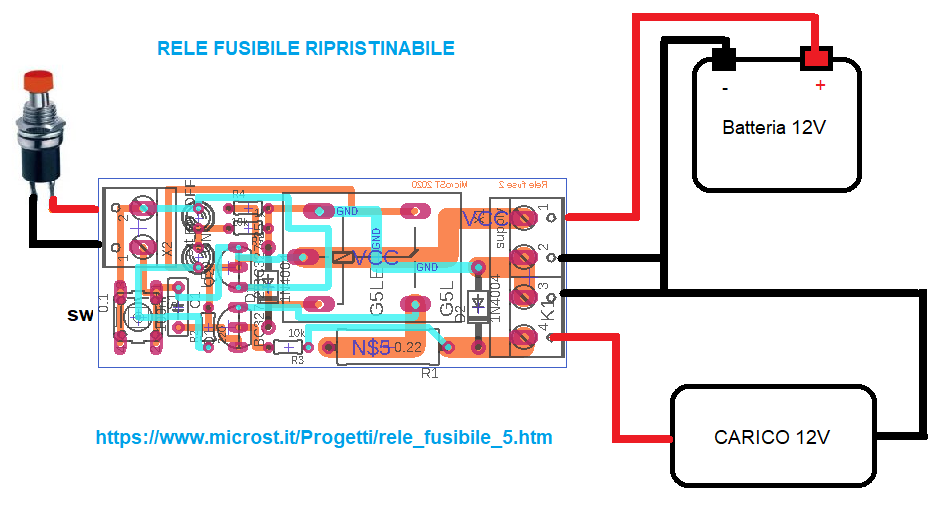
PCB of the final version of the fuse relayThe connector SW has been introduced to connect any external reset switch (SW_external) in addition to the one already present on the PCB and two LED diodes: green to indicate the status (ON) and red to indicate the activated protection status (OFF).
Below is the application diagram of the resettable electronic fuse:
In the following photos the circuit realization of the fuse relay for 12V loads with 3.5A intervention threshold:
Simulation result


Comments
Please log in or sign up to comment.