For applications with low power asynchronous motors, an inverter has been designed with the initials MST_K05VF. This is a VFD mini inverter with which you can regulate all asynchronous motors with powers up to 500W (just over 0.5Hp). It is particularly suitable for controlling fan motors (axial and tangential), pillar drills, asynchronous washing machine motors (old style).
The regulation is of the scalar type with the V / F technique: the frequency F and the amplitude V of the power supply sinusoid are varied, keeping their ratio constant in order to keep the stator flux constant and therefore the torque of the motor. The architecture of the inverter is the same as that of the MST_KVF inverter. The substantial difference lies in the power stage which is made with an intelligent power module (IPM = Intelligent Power Module) which allows for a compact and optimized circuit in the management of power and any faults (short circuits, overheating, etc.).
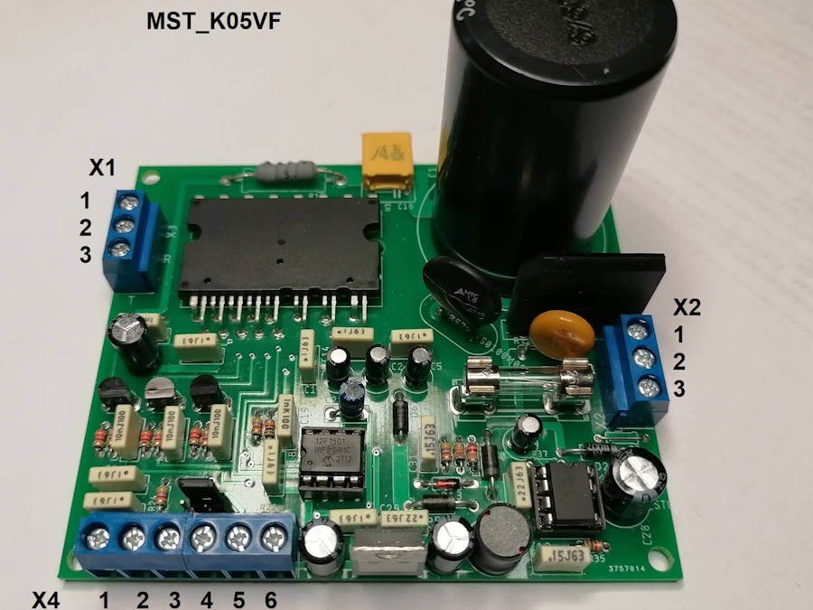
Mini inverter VFD MST_K05VF photo
Particular attention must be paid when handling the inverter as the metal parts present may be under the grid with consequent danger of electric shock.
Electrical characteristicsThe following table shows the main electrical characteristics of the MINI inverter VFD.
* thermal sensor (NTC) inside the power module
Operations and functions of the inverterThe MST_K05VF inverter is simple to use: just connect the AC mains power supply, the motor, to the respective connectors and drive the SS and VC inputs. In manual mode, starting and stopping the motor is activated by means of a switch (START / STOP function), while the motor speed is selected by means of a potentiometer.
- Soft Start and Soft Ramp function
In order to avoid high inrush currents both at start-up (starting from standstill) and during the change of speed setting, an acceleration / deceleration ramp is applied when passing from one adjustment value to another. In the case of starting from a standstill we speak of a soft start acceleration ramp while during operation we speak of a soft ramp which can imply an acceleration or deceleration ramp.
- Speed setting
The motor speed value is set by means of the voltage applied on pin VC of connector X4. Through the voltage on VC, the pair of values Amplitude_Rms - Frequency of the output sinusoid is chosen. The adjustment range starts from the 220Vrms - 50Hz (full power supply) to the minimum value of 49.5Vrms - 11.25Hz for an input voltage of Vin = 220Vrms (312.5 Vmax).
In the manual application, VC pin is powered by the central terminal of a potentiometer powered by GND and V5V pins of connector X4 . In other control mode, this voltage could be supplied by an external board (PLC, Arduino, etc).
There are 32 possible selectable values (the step is 1.25Hz). The ratio between voltage and frequency is kept constant for the whole adjustment range at the value of 220/50 = 4.4. For example, for a 4-pole motor the rotation speed RPM is a function of the frequency f and the number of poles P according to the formula:
RPM = 120 * f / P
defined as described in the AC motor tutorial
For f = 50Hz and P = 4 the (maximum) rotation speed is RMP_max = 1500 rpm. The minimum speed of the motor is for f = 11.25Hz or RPM_min = 337.5
Protections
- SAFE START
The Safe Start function is a protection that prevents the motor from being activated when the circuit is powered by the user or for resetting the mains voltage following a power cut. To activate the inverter, the user must go through the STOP position and then go to START.
- Thermal protection (OTP) and overload (OLP)
The inverter has protections to safeguard the integrity of the output stage: OTP (Over Temperature Protection) thermal protection and OLP (Over Load Protection) overload protection.
The OTP protection is activated by switching off the final stage (present inside the IPM module) when it reaches the temperature of 100 ° C. The NTC sensor is present inside the IPM module.
The OLP overload protection activates when the load current exceeds a threshold or when there is a short on the output line. The activation threshold depends on the value of the sensing resistor chosen: when the voltage across the sensing resistor, due to the current flowing in the load, exceeds the threshold of 0.47V, the protection is activated and the output stage is switched off very quickly. These protection are latched and to reset them it is need to execute a STOP/START sequence .
- Status monitor
Through the value of the SS and FOUT signals of connector voltage values of the SS and FOUT pins of the X4 connector. It is understood that these functions make sense for a regulator powered correctly by the VIN. (J1 connector configured to have FOUT on pin2 of the X4 connector).The X1 connector is the output connector to which the motor must be connected.
Summary table of the inverter status as a function of SS and FOUT
** SIG = square wave signal with frequency equal to that of the output sine wave
When the protections are activated, in order to restart, the START / STOP command must first be placed in the STOP position and then in START after having waited a few seconds for the output stage to cool or the overload condition removed.
Description of the inverterWe describe the mapping of the various connectors present in the inverter board referring to the following photo:
Photo of the inverter MST_K05VF highlighting the connectors
X1 connector is the output connector to which the motor must be connected.
X2 Connector is used for mains power VIN:
X4 connector it is the control connector with which the regulator is activated/deactivated, the speed/frequency is set and the 5V power supply voltage is taken for the potentiometer or to power external control cards
Connector J1 is used to direct the FOUT signal or the NTC voltage via jumper on pin 2 of the X4 connector
To select FOUT on OUT you need to put the jumper between pins 1 and 2. If you want to bring NTC to OUT you need to put the jumper between 2 and 3.
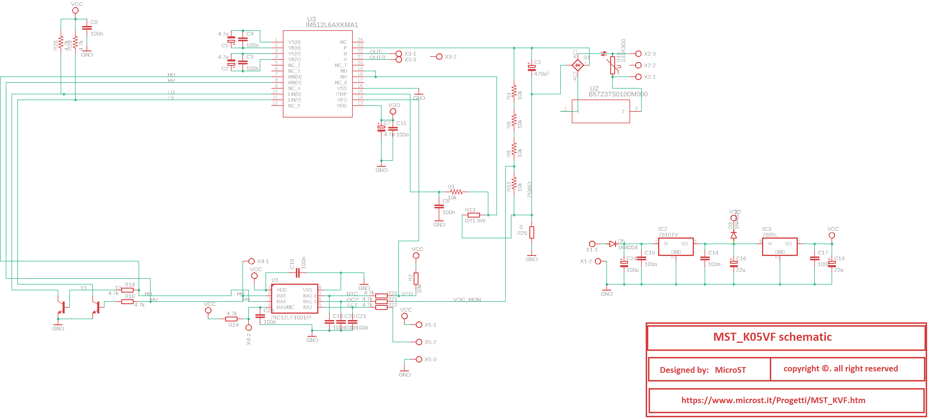
Place 2 of the X4 connector has a double option. From this pin it is possible to read the frequency of the sinusoidal output signal or an NTC voltage which represents the temperature of the output stage integrated in the IPM module. The NTC signal is a voltage that represents the temperature of the output stage. This voltage is generated by a divider, powered at 5V which has a resistance of 4700 ohm as its high side and the NTC incorporated in the IPM module as its low side.
Below is the voltage - temperature correspondence useful for implementing temperature measurement (for example with Arduino)
VNTC (V) / TEMP (°C)
4.89 /5
4.87 /10
4.83 /15
4.79 /20
4.74 /25
4.68 /30
4.61 /35
4.52 /40
4.43 /45
4.32 /50
4.20 /55
4.07 /60
3.92 /65
3.76 /70
3.60 /75
3.42 /80
3.24 /85
3.05 /90
2.86 /95
2.67 /100
2.48 /105
2.30 /110
2.13 /115
1.96 /120
1.80 /125
VNTC voltage - temperature correspondence
Basic application scheme - manual mode
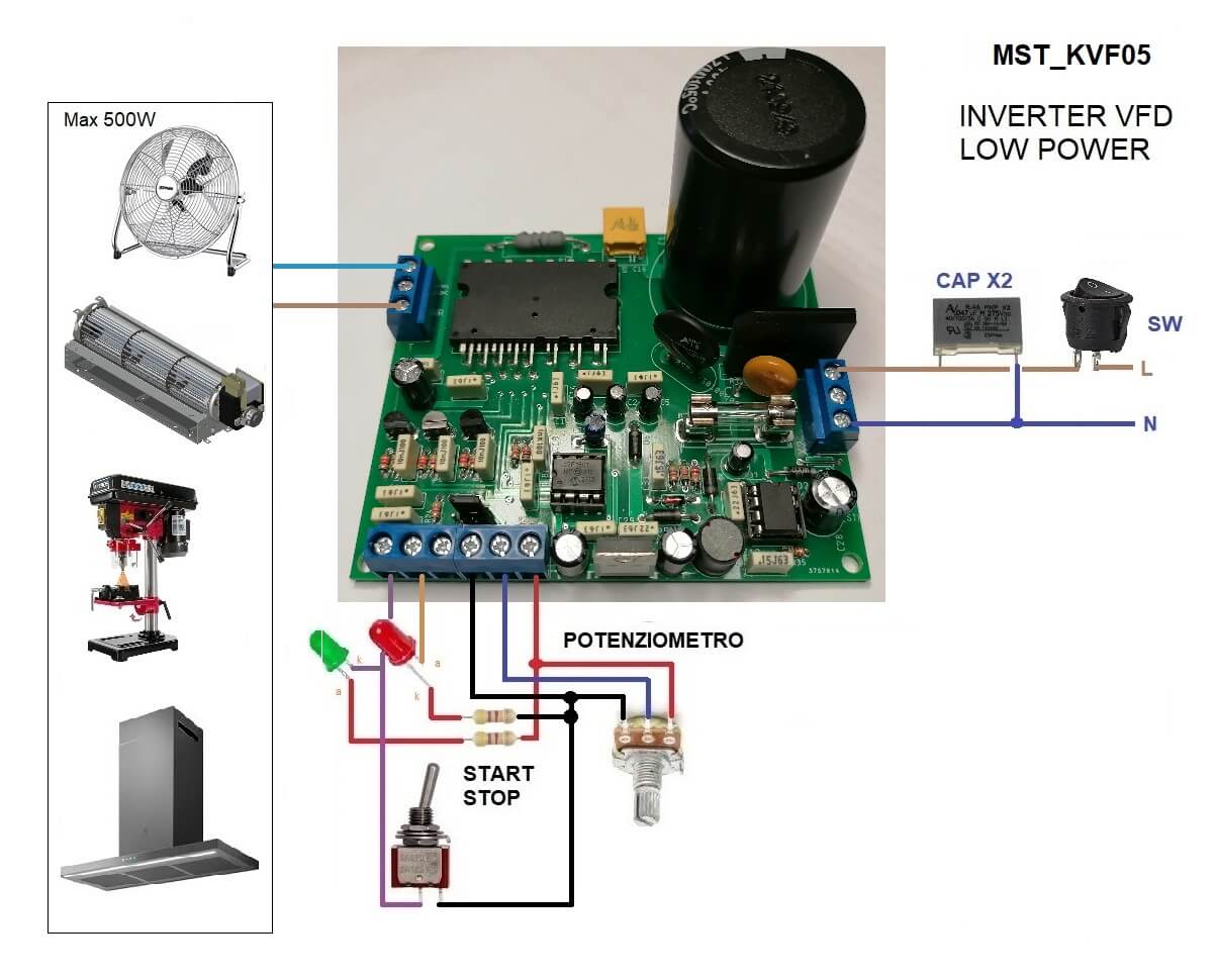
The following photo shows the connection diagram of the MST_K05VF inverter in the basic or manual mode:
Application diagram of the MST_K05VF - manual mode
For a simple application in manual mode, it is necessary to apply the mains AC voltage, a fuse, a switch and a 150nF type X2 capacitor. If you want you can also put an EMI filter.
The START / STOP switch allows to setting the START and STOP operations. The green LED indicates the inverter status (ON = on, OFF = off) while the red LED indicates the motor status (ON = on OFF = off).
The speed setting (voltage / frequency ) is set by means of a potentiometer which generates the voltage VC from the 5V voltage bus.
For heavy use, the output stage must be equipped with a heat sink which is applied to the upper surface of the IPM module and fixed by means of screws that pass through the PCB (already drilled) and in the notches provided on the module.
Board sizeThe dimensions of the board are shown in the following photo: All anchor holes are 3mm away from the edges. Each hole has a diameter of 3.5mm.
Drawing of the PCB of the MST_K05VF with dimensions expressed in mm
Particular attention must be paid when handling the inverter. The metal parts may be under the HV voltage with consequent danger of electric shock.
MST_K05VF - Other applicationsThe MST_K05VF inverter can be used not only in manual mode but also as a power part / actuator of an external control system: via the control connector it is possible to control the regulation level, switching on and off from the outside, monitoring the status as well as taking the power supply voltages (5V) for the external circuits (Arduino boards, sensors, etc.). The following photo shows an example diagram of how it can be interfaced with a generic card.
MST_K05VF as actuator controlled by external board
As shown in the figure, external control can be implemented by a micro board such as Arduino or via PLC. By piloting the SS input you can control the starting and stopping of the engine. By reading the voltage present on Fout/NTC you can obtain the frequency of the output sinusoid or the temperature of the final stage (depends on how connector J1 is configured). Through the VC input you can control the regulation of the motor speed (torque, voltage, frequency according to the V/F curve). This input accepts a voltage that can vary from 0V (speed @11.5Hz) to 5V (speed @50Hz).
Therefore, only 5 wires are needed to connect the MST_K05VF to the Arduino board: 2 for power and 3 for control. In particular, SS and VC must be driven by digital I/O lines while the NTC line must be analogue inputs. These assumptions imply choices on how to configure the ports of the Arduino board connected to NTC, SS and VC.
The 5V power supply voltage can be taken from the GND and 5V terminals (place 4 and 6 of the inverter.
As regards the SS signal, the relevant Arduino pin must be configured as input. As per the table on page 2 relating to the X4 connector, the SS signal must be left free, polarized by an internal pull-up, to give the STOP function while it must be put to GND to activate the START. If we therefore want to drive this function with Arduino we must define it as input to give the STOP and define it as output, forcing zero, to activate the START function. In the first case, by setting the Arduino pin as input, we let the input of the MST_K05VF be polarized by its internal pull-up while, in the second case, by setting it as output we force it to zero, i.e. as if we were putting the signal to GND. In practice we are creating an open drain I/O.
Another matter is for the VC entry. A voltage between 0 and 5V should be supplied to this input. If the Arduino board has a DAC peripheral then it is best to connect the relevant Arduino output to the VC input and that's it. However, if the Arduino board does not have a DAC then a PWM signal is used to generate the control voltage on VC. The direct voltage can be obtained from the PWM signal via an LPF (low pass) filter placed downstream of this signal. (I suggest reading this PWM_APP tutorial). This LPF filter is already present and is placed between the VC input and the micro pin to which it is associated with the ADC converter input. By varying the duty cycle of the PWM signal from 0% to 100% we will obtain a voltage from 0 to 5V at the regulator input. So by varying the duty cycle of the PWM signal we vary the speed of our motor. As the Arduino pin, choose one of those that can generate a PWM signal. The PWM signal has 256 possible duty cycle levels which means we have 256 regulation values!!!
The NTC signal is a voltage that represents the temperature of the output stage. Using the voltage - temperature correspondence shown on page 2 of this article allows you to measure the temperature of the output stage and view it on the display.
IMPORTANT!!! The MST_K05VF board is not isolated from the AC line, therefore any external board, connected to the inverter, must be powered from the AC line in a galvanically isolated way.
Italian version of the article can be read in the microst web site MST_K05VF


Comments
Please log in or sign up to comment.