


Hardware components | ||||||
 |
| × | 1 | |||
| × | 1 | ||||
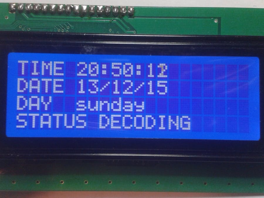
The project presented in these pages is a decoder of the DCF77 radio signal transmitted on the frequency of 77.5 kHz. This signal, transmitted by a German broadcaster, contains time and weather information certified by an organization based on atomic clocks. In daily practice, this signal is used to synchronize European continent clocks (airports, trains, metro, etc) and also contains weather information accessible only on a paid license. In the following photo our DCF77 decoder during reception and decoding. It decodes the DCF77 signal and displays the information contained therein on the LCD display. The DCF input signal to the decoder must be a sequence of positive pulses representing the one and zero of the original signal. The signal as required by the decoder in the following pages defined as "digitized" can be taken directly from the output of DCF77 receivers available on the market from electronic sites or generated by an interface shown on the following pages which transports the audio signal of a 77.5kHz tuned radio receiver or better still output audio from a PC jack, tuned to the DCF77 signal via an SDR-powered receiver via WEB !! The information in the DCF77 signal is transmitted using an ASK modulation obtained by lowering the transmitter power by 25% at the bit. If a "one" bit is transmitted, the lifetime of the carrier is reduced to 200ms, while when it is "zero" the time is 100 ms. In the figure the screenshot of the modulated carrier signal in the case of a bit one and zero. Each bit lasts for 1 second and 59 bit sequences are transmitted. The following figure shows the sequence of bits and their meaning. Data is encoded in BCD:
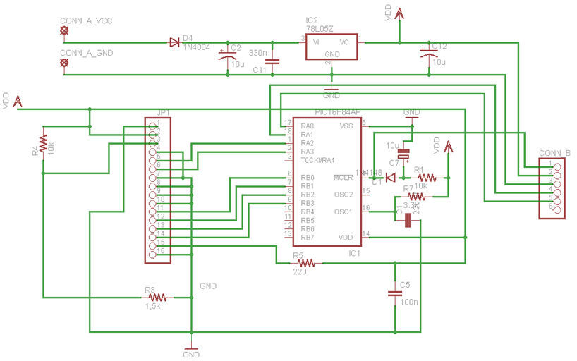
As you can see, the DCF77 decoder card is directly connected to the connector of a 4X20 LCD display, it has a CONN_A power connector, a CONN_B interface connector to connect the receiver / scanner card that must provide the decoder with a positive pulse Bit transmitted correspondence.
1) NC; 2) NC; 3) DCF digital signal; 4) GND 5) VCC 6) NC
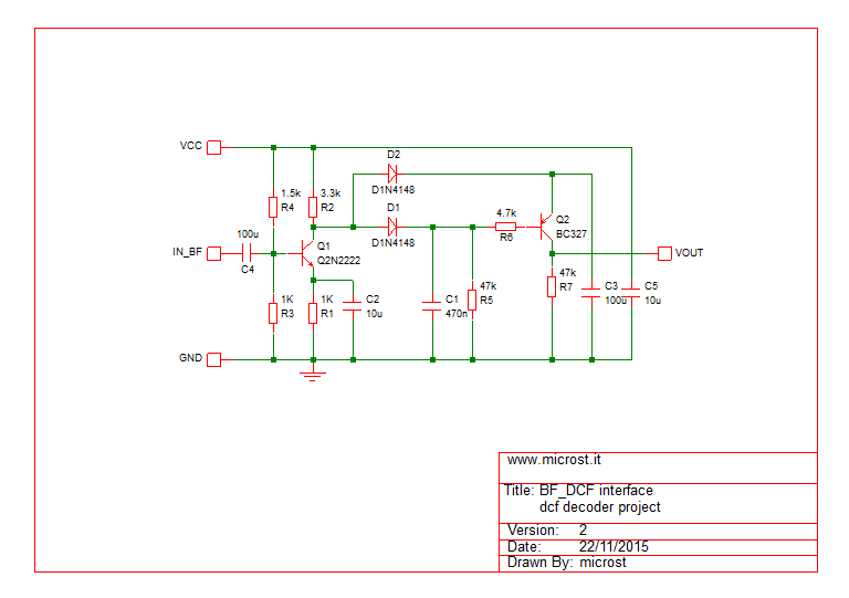
In the following photo, the assembled BF_DCF77 interface is shown.
The following picture shows the connection of the BF_DCF77 interface with the decoder. Three wires start from the decoder: 2 for the power supply (red and black) and the (white) input data provided by the card. As input, the BF_DCF77 board receives the audio signal output from the receiver or audio output of the PC if you use the WEB receiver
WEB Radio dcf decoder
BF interface

Comments
Please log in or sign up to comment.