This is a fun reaction timer game using a 4 digit 7-segment LED display an Arduino and a button. Challenge yourself or your friends to beat the LOWEST reaction time. Can you go even lower?!
The game starts off by flashing the high score (which is initially set to 9999). The idea is to get the LOWEST score possible by beating the previous high (low) score. Press the button to start the game. '8888' which flash a few times, along with a few tones from the piezo, to indicate a game is about to start. Then the display goes blank and the game is about to start. Now the Arduino will wait a random time between 2 and 10 seconds. Then, the counter starts counting up in milliseconds accompanied by a rising tone on the piezo/speaker. Your job is to press the button as soon as you see the digits counting up as quickly as you can. If you are lucky you will beat the high score and your new score now becomes the new high score. If you fail, you get the two fail notes and the game goes back to the start.
I got this idea after acquiring an Elegoo Uno Super Starter Kit and was trying to come up with some ideas of what to do with some of the parts. The kit comes with a 5641AS common cathode 4-digit 7-segment LED display, plus the usual buttons, resistors, etc.
You will need an Arduino Uno or Nano, a breadboard, jumper wires, the 5641AS (or any other 4-digit display) 4-digiti 7-segment LED Display, a button, 7 x 220ohm resistors and a piezo sounder or speaker.
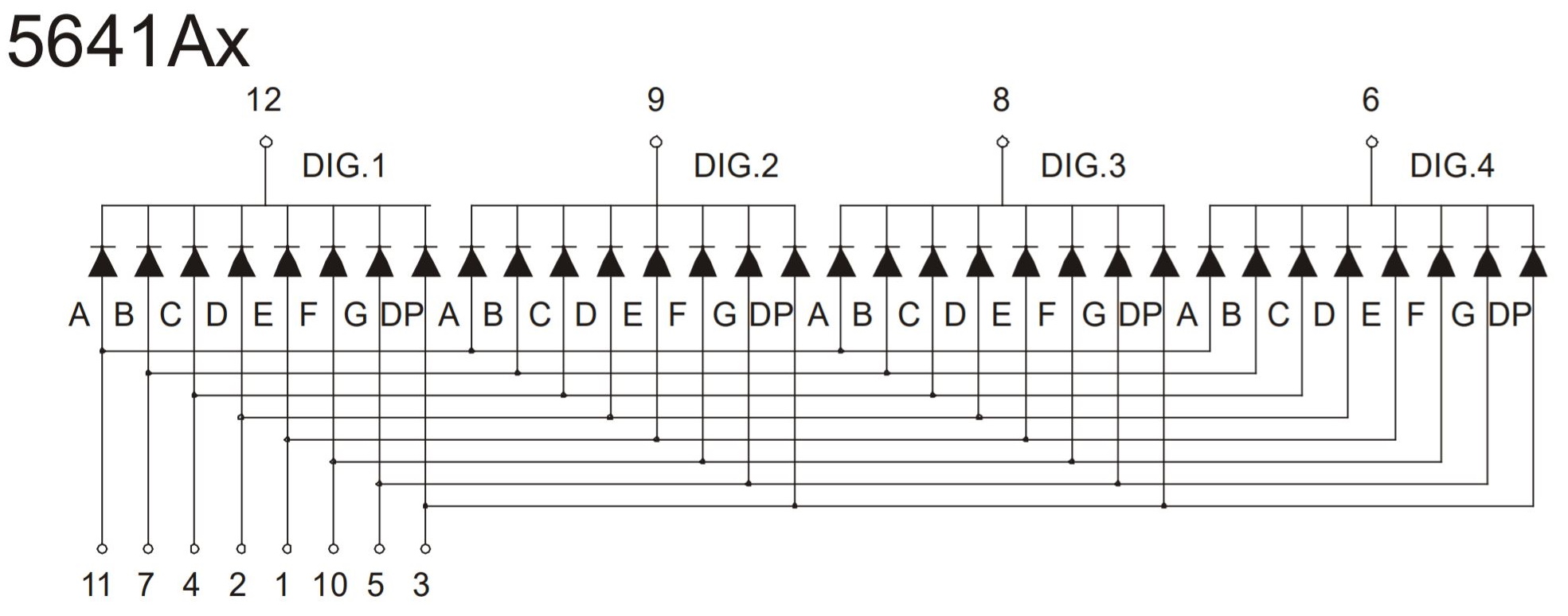
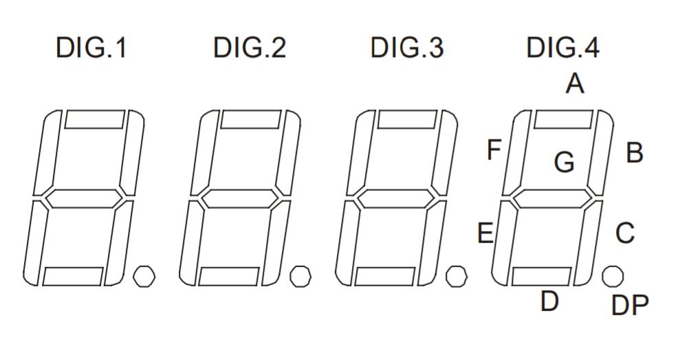
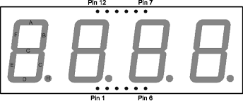
According to the datasheet the pins connect to the display like so..
The display is common cathode which means the digit pins (12, 9, 8 and 6) need to be pulled LOW to activate a digit. Each of the 8 LED segments on the display are turned on and off with pins (11, 7, 4, 2, 1, 10, 5 and 3). We will be using the SevSeg library to control the display.
First, get your 7 x 220ohm resistors and snip the legs down to about 50% of their size. Then bend the legs over like so...
Now insert the display and the resistors into the breadboard like this:
Now connect 7 jumper wires from the BOTTOM of the resistors in order from left to right to pins 11, 7, 4, 2, 1, 10 and 5 in that order. It should look like this:
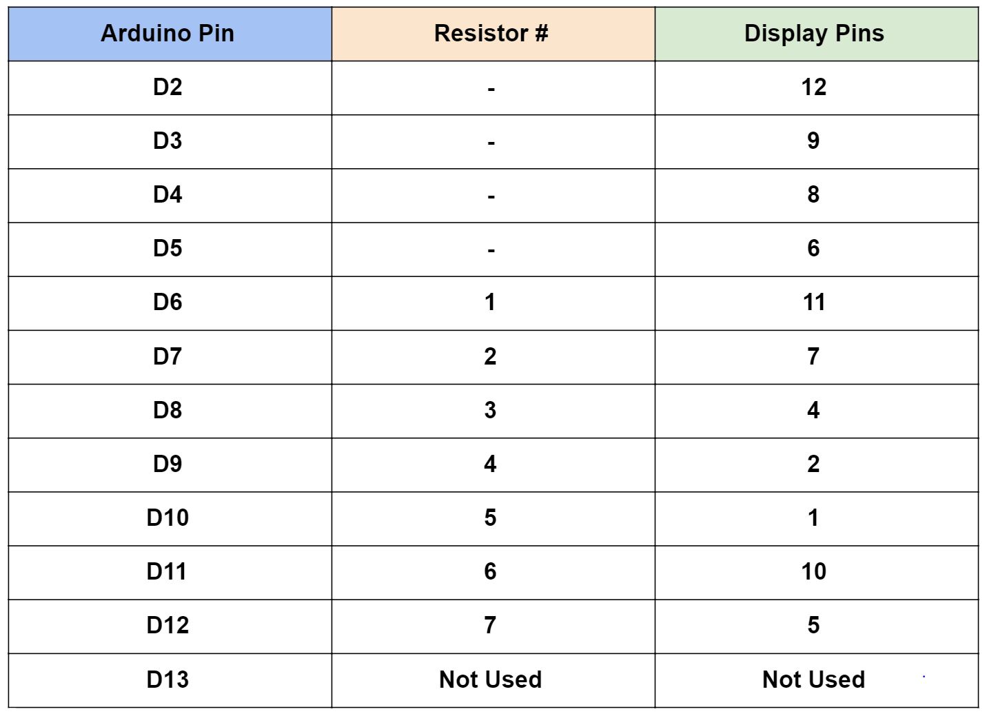
Now connect jumper wires from digital pins 2 to 5 on the Arduino to pins 12, 9, 8 and 6 on the display, in that order. Then further jumper wires from digital pins 6 to 12 on the Arduino across to the top of the resistors from left to right.
The table below shows what pins on the Arduino go to which resistor and/or display pin.
Now add a button as in the photo above. The left hand side of the button connect to Ground and the right hand side connect to Analog Pin A0 (D14).
Connect a piezo sounder or speaker (I've used a small terminal block to help) with the black wire going to Ground and the red wire going to Analog Pin A1 (D15).
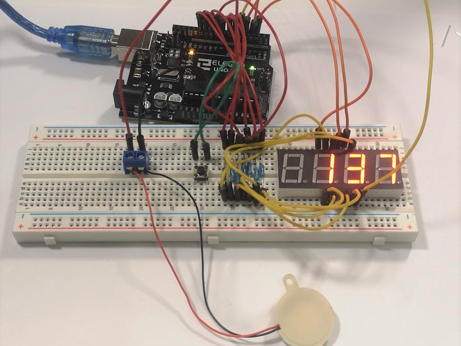
Once everything is connected you will have a spaghetti explosion that looks like this:
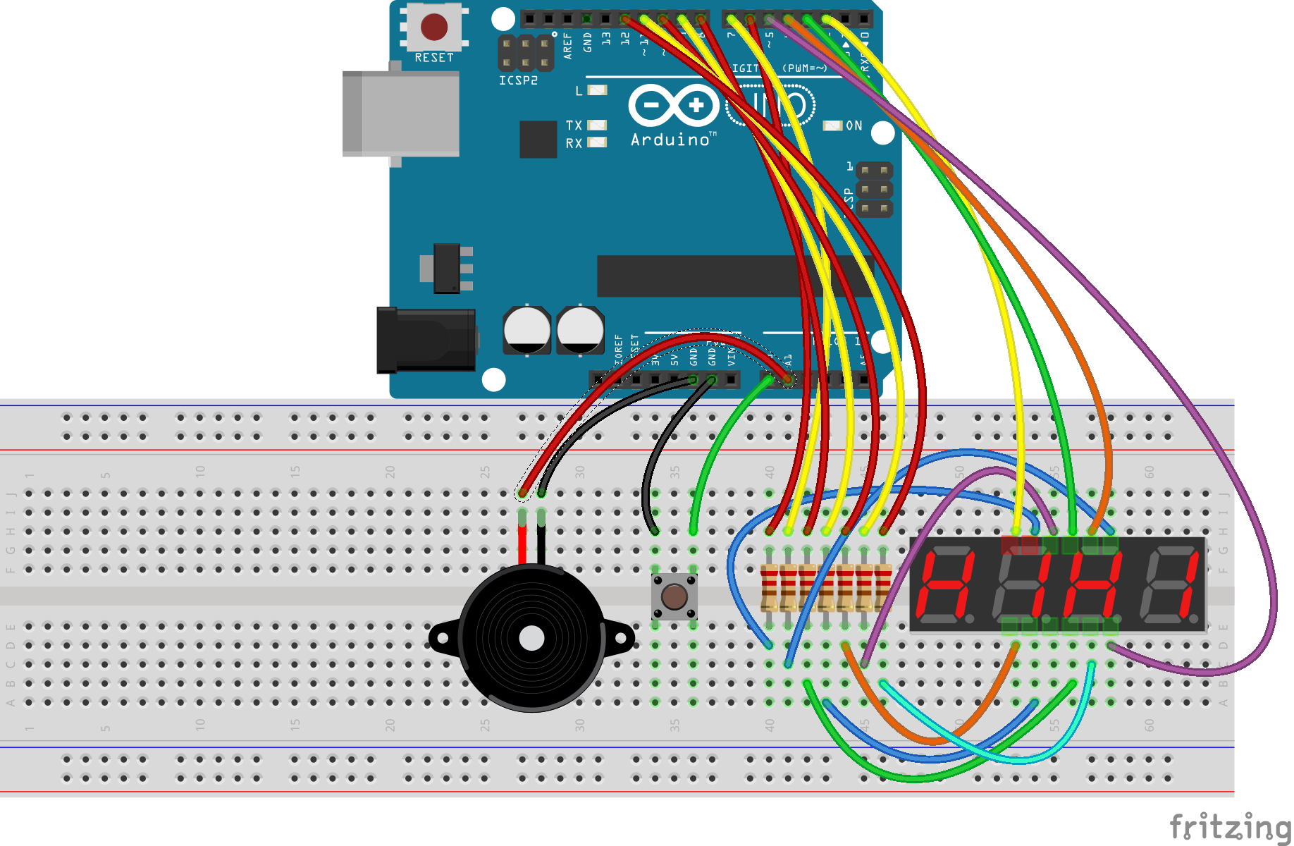
Here is a Fritzing diagram that may or may not help:
Now download the code from my GitHub repository HERE.
Click the green CODE button, then DOWNLOAD ZIP. Download the file, unzip it and then open the reactiontimer.ino file with the Arduino IDE. Upload the code to your Arduino and off you go! Have fun. Any questions let me know and I will do my best to answer.
Cheers,
Mike


_ztBMuBhMHo.jpg?auto=compress%2Cformat&w=48&h=48&fit=fill&bg=ffffff)




Comments
Please log in or sign up to comment.