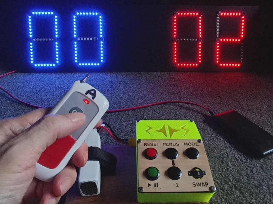
This project was created to be a low-cost and convenient way to set and display the scores of a game, especially for a Drone Soccer match. But it is also suitable for most games where two teams or players score against each other in a match. The video below demonstrates how it is operated.
It comprises an LED Scoreboard built using individually addressable 5V LED strips (WS2812B) with a wireless RF 433MHz receiver module on a compatible Raspberry Pico microcontroller (see Arduino IDE Setup section for the details on why this microcontroller is used). The LED Scoreboard receives remote signals from compatible RF 433MHz transmitters. I also built a separate custom Control Console transmitter (as shown in the video) using an Arduino Uno and an RF 433Mhz transmitter module. But this build is optional, as any commercial RF433 remote transmitter with six or more buttons can be used instead. The two-button remotes used to increment the scores are from the seller at: https://vi.aliexpress.com/item/1005005797926289.html, who also has versions with different numbers of buttons.
(Not shown in the video is the use of the "Off" button on the two remotes. In a Drone Soccer match, there are two goalposts and each has a wireless switch that triggers a red light to switch on when the scorekeeper presses the "On" button of the corresponding remote upon a valid goal. The red light remains lit until the scorekeeper sees that the striker's team has returned behind the midfield and then he presses the "Off" button to switch off the goalpost red light to indicate that the striker is allowed to strike again. Therefore, the "Off" button on the remotes does not affect the scoreboard. Watch this official Drone Soccer match to see how goalpost lights are used in a match. Or read the rules of Drone Soccer here.)
The CircuitThe wiring of the components used in the scoreboard is shown below. The data out pin for the RF receiver has to go to the interrupt pin of the processor, which is the GPIO pin labeled 1 on the Raspberry Pico (or labeled 0 on compatible RP2040 Core boards). Data pin 7 on the Pico outputs to the LED strip Din pad. A capacitor should be connected in parallel to the input voltage points as close to the first LED as possible to protect it from damage due to the surge in current at power up.
See the hi-res version of the circuit at: https://svgshare.com/s/15K_
The sources for the main components are:
- Compatible Raspberry Pico RP2040 Core Board - https://vi.aliexpress.com/item/1005004096147070.html
- WS2812B LED Strip - https://vi.aliexpress.com/item/1005005273272915.html (I used 96/m black non-waterproof)
- 433MHz RF Receiver - https://vi.aliexpress.com/item/1005004988421038.html
- USB A Connector Power Cable - https://vi.aliexpress.com/item/1005002876674759.html
If you are new to WS2812B LEDs, I highly recommend reading this article first - https://lastminuteengineers.com/ws2812b-arduino-tutorial/.
The LED strips must be arranged and connected in a snake-like "S" sequence, as shown:
Each segment of a digit is a strip of seven LED pixels. Each digit has seven segments, so the total LED pixels required will be 196. You can also choose to have more or less number of LED pixels per segment by changing the number in the line of the program that specifies the number number of LED pixels in each segment:
#define LED_per_SEG 7 // number of LED pixels in one segment of a digitIf you are wondering at this point, why I did not split the display into two groups of LEDs and use two GPIO pins on the Pico board to control the display of each group of LEDs separately, please refer to this issue I encountered with the Raspberry Pico RP2040 Arduino Core firmware.
The most tedious part of the project for me was connecting the LED strips to form the seven segments of each digit. This is because I opted to use the shortest length of wires possible, As a result, stripping the insulation off each wire for soldering and getting their lengths correct to make the 90° bend was quite a formidable task to accomplish for the many 90° bends needed. While using longer wires would reduce this difficulty, I didn't want to deal with tucking away longer wires to avoid a messy-looking board. In hindsight, I should have gotten these ready-made L-shape connectors to try. If you have experience with such connectors, please let me know how well they work for you in the comments!
Be sure that the orientation of every strip is correct before connecting them (pay attention to the small arrow markings on the strips). If the Din and Dout pads on the strips are not facing the correct order, the LEDs will not work. Again, please read https://lastminuteengineers.com/ws2812b-arduino-tutorial/ if you are not sure of what to do,
This is a prototype so I did not spend too much effort to enhance the aesthetics of the assembly. I simply mounted everything onto a hollow 5mm polypropene board I had obtained from this local supplier.
Only the LED strips are prominent from the front of the board after covering up the short wires between the LED strips with black hot glue. All other components and wires are routed to the rear of the board and secured in place with black cloth tape. You can use any method to prop the board but I placed it on this foldable easel stand. A USB power bank or USB charger rated 2A or higher can power the scoreboard (a higher-rated power bank may be needed if using more than seven LEDs per segment).
To compile the program successfully, the Arduino IDE needs the following to be installed:
Library Manager:
rc-swtich
SafeString
FastLED
Boards Manager:
Raspberry Pi Pico/RP2040
The reason for using this particular board for the project is its ability to utilize the duo core capability of the hardware. So other firmware for RP2040 will not work for this project. This video explains how duo core programming is done in Arduino IDE - https://www.youtube.com/watch?v=w5YigjvSaF4. My scoreboard program uses the first core to run the tasks for receiving and processing the RF signals, while the second core is programmed to run all the tasks relating to controlling the LEDs with the FastLED library. Only in this way could both functionalities work properly for the scoreboard.
During the compilation process, you will see a bunch of red warnings but the process will still be successful once the white text appears at the end (provided you don't introduce other errors in the program).
It is necessary to change the RF codes in these lines of the program to the ones matching the codes from your remotes:
To know the RF codes from each button on the remotes, the scoreboard must have the program running and connected to the Arduino IDE with the Serial Monitor opened. Each time the scoreboard receives an RF signal in the 433MHz range, it will display the RF code value in the Serial Monitor. Copy the RF code value for each button press of the remotes and input them into the program accordingly.
If you are keen to custom-build the Control Console, you can find the Optional Arduino Sketch in the Code section and the relevant STL and SVG files to 3D print and laser cut the parts to make the case in a zip file in the Custom parts and enclosures section.
The push buttons are from: https://vi.aliexpress.com/item/1005003035314381.html. Any slide switch or toggle switch can be used for the SWAP switch as long as it fits into the opening of the faceplate. I used an Arduino Uno as the microcontroller to transmit the signals through an RF 433MHz transmitter module, but any microcontroller with enough GPIOs should work too.
The hi-res version of the circuit wiring above is at - https://svgshare.com/s/15JT.
I also added a step-down converter to allow for the option of using an external 2S or higher Lipo battery as a power source, even though it works fine when connected to a USB power bank via the Arduino Uno's USB port.
If you have limited time and resources to do this, I recommend purchasing an RF 433MHz remote with six or more buttons such as the ones shown below (a remote with more than six buttons is recommended for adding features in the future):
You can buy one from the same vendor as the one where I bought the two-button remotes- https://vi.aliexpress.com/item/1005005797926289.html. I have found these types to work best in range and responsiveness compared to other keychain types in the market. So do your research if you decide to try other types of RF 433MHz remotes.
Final ThoughtsThe prototype has been tested and is still in use by the Association of Drone Soccer Singapore and is working in tandem with their goalpost lights operation based on the rules of the game by FIDA. Although it functions accordingly, it is by no means a foolproof system for two reasons: Firstly, the lack of duplex communication means there is still the possibility that only the scoreboard or the goalpost registers the "On" button press from the scorekeeper's remote; this will lead to error in the score capture. Secondly, the RF 433MHz system is not a secure protocol and can be vulnerable to signal intrusion or jamming. So for use in high-stakes matches, please keep these limitations in mind.
Finally, the original vision for the design is to have the Control Console also wirelessly control another LED display that shows the remaining time of the match, and an audio system that broadcasts countdown information at certain intervals during the match. That is why an unused button labeled with the play-pause icon is currently on the custom Control Console. I do not know if I will ever find time to work on this, but I hope the feature gets built by someone if not me. :)
Addendum - How to Add Wirelessly Controlled Goalpost Lights to the Drone Soccer GoalpostsIf you are making this scoreboard specifically for Drone Soccer matches and would like to add a DIY red indicator light to each of your Drone Soccer goalposts, you can purchase these two components to build one and power it with a USB power bank or any 5V source:
RF 433MHz Switch - https://vi.aliexpress.com/item/1005005011296616.html
5V Red LED Strip - https://vi.aliexpress.com/item/1005003307581709.html
Watch the video below to see how to set the RF switch to bind it with any compatible RF Remote Controller. For our case, the binding should be done using the Latched mode procedure (watch from 1:50 onwards).


_ztBMuBhMHo.jpg?auto=compress%2Cformat&w=48&h=48&fit=fill&bg=ffffff)


Comments
Please log in or sign up to comment.