Yet another Arduino LED clock: A decorative desktop / wall clock featuring *internet time * via WiFi and one-touch-activation... ;)
This little project was an excercise / homework for the German openHPI-Kurs Wie programmiere ich meinen ersten Mini-Computer?. ('How do I program my first mini computer?').
The course featured a customized version of Ardublockly (a visual programming editor for Arduino based on Google's Blockly) and the task was to implement and describe a physical computing project soley by using this tool.
BOMComponents- ESP32 microcontroller development board (e.g. the ESP-32 Dev Kit C)
- 12Bit RGB LED ring WS2812 (e.g. the NeoPixel Ring - 12 x 5050 RGB LED with Integrated Drivers)
- Breadboard, half-size
- Jumper wires
- Battery (e.g. a 5V power pack)
- Picture frame (deep enough to house the device - e.g. the RIBBA frame by IKEA)
- One-cent-coin
- Glue (e.g. hot glue)
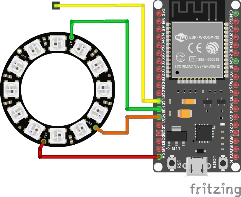
Connect the LED ring with the ESP32 board as follows:
ESP32 pinLED ring connectorWire5VPWRredGNDGNDorangeG12DIgreen
@ 12bit RGB LED ring WS2812Connect
- a red wire to PWR connector
- an orange wire to GND connector
- a green wire to DI connector.
Connect
- the red to pin 5V
- the orange to pin GND
- the green to pin G12
- a yellow to pin G14
via the breadboard.
The yellow wire will be connected to the touch sensor (i.e. the one-cent-coint).
- Create, print and cut in size a nice picture for the clock face regarding the diameter of the LED ring. (e.g. like this one).
- Place the picture into the frame.
- Place the LED ring on the back side of the picture and fix it there with glue.
- Place/glue also the breadboard with ESP32 board inside the frame.
- Connect the yellow wire (connected to pin G14) to the one-cent-coin and fix the coin on a back corner at the frame.
If you want to use Ardublockly, open the file12_RGB_LED_Ring_Clock.xml (here) in Ardubockly and click the IDE button.
- Since Ardublocky somtimes f.cks up some variable identfiers it might be necessary to change the identifier
myLedRingwith in the Setup led strip back to it's correct value. - The blocks regarding serial communication should be only activated for debugging purposes, since the use of Serial might interfere with the Neopixel library's functions.
or
Arduino IDEOpen the file 12_RGB_LED_Ring_Clock.ino (here) with the Arduino IDE, compile and transfer to device.
After powering-on the device, it...
- tries to establish the configured WiFi connection,
- tries to receive the current time via NTP,
- displays the time for about 15 seconds
- and then switches off all LEDs.
When the coin is touched it will display the current time again. After one minute the display will go dark again till the next activation by touch.
Time will be displayed by the light colours of the 12 LEDs:
- Hands between two positions (1-hour / 5-minutes / 5-seconds) are displayed on two neighbouring LEDs with adjusted brigthness.
- Hands covering each other will be displayed by mixed colours.


_izMmHFy93f.jpg?auto=compress%2Cformat&w=900&h=675&fit=min)


Comments
Please log in or sign up to comment.