In an era where artificial intelligence (AI) and robotics are transforming our daily lives, creating an AI-powered autonomous room rover is an exciting project for any tech enthusiast. I have always wondered how it feels like to build this idea from the ground up alone with limited resources I have available. This rover bot is designed to navigate a room autonomously, avoiding obstacles and responding to voice commands.Imagine having a companion rover bot who actually knows you by name and serves you tirelessly (well while 🔋 is full :) ). I am designing A2R3 as an open cost effective diy robotic platform for all who want to customize their own rover bot.
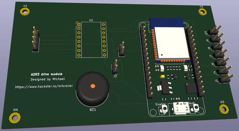
CAD preview
This project will guide you through the process of building your own intelligent rover using readily available components and open-source software step by step. I divided this project in three parts for simplicity.
WELCOME to the first series part1: building the Chassis and test it by implimenting simpleobstacle avoidance system.
Objectives
Autonomous Navigation: Enable the rover to move around a room without human intervention, avoiding obstacles. (Part1 series).
Real-Time Feedback: Implement sensors and wheel encoders for real-time data collection and response. (Part2 series)
Interaction: Incorporate image recognition using trained AI model to control the rover’s movements in "follow me" (Person following) mode and for object detection. Implement SLAM using ROS2 (Part3 series)
Components Required
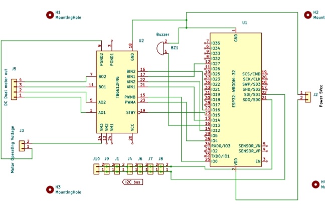
Microcontroller: using ESP32 (micro-ROS) VS Raspberry-pi (test comparison)
Motor Driver: TB6612FNG Dual H-Bridge Motor Driver
Motors: 2 DC 6V geared Motors with wheels
Circuit board : To solder every component prototyping then design custom PCB
OLED 128x32display : To display status of the navigation and other information
Buzzer : To sound "beep" on status display with the OLED display
MiniCooling fan : To cool off the TB6612FNG DC motor driver
Chassis: simple plastic chassis 3D printed and designed
Sensors: VL53LOX time of flight sensor
Power Supply: Battery pack 20 V Lithium-ion to power the motors and all the circuits to the BOT including sensor, camera, and lights.
Miscellaneous: Jumper wires, buck DC-DC step down converters,prototype PCB boards, mounting hardware, and a chopping board straight out from the kitchen 😀 👌.
Software Requirements
Operating System: Linux or windows Arduino IDE installed ( I recommend working on Linux (Ubuntu) for future navigation (NAV2) and SLAM development system to use ROS2 or micro ROS)
Programming Language: C++
Hardware Requirements
Plastic foam tires are great for this project and they are lightweight, hard and have a good grip. Relatively less costy.
The actuator to drive the rover is plastic agearbox. It has a 6V DC motor inside and produce a fair amount of speed with a high torque strong enough to drive the rover with up to 15kg amount of payload. (I Iet my 15kg son drive on it). In the future I will do some other scientific tests.
Assembly
1 / 6 • The Base-board Drive unit with ESP32
Algorithm
obstacle avoidance
Drive forward until obstacle is detected. If Obstacle is detected then stop for few seconds then move backwards for few centimeters. Then move again try if still there is the obstacle. If the obstacle is there move backwards and turn right for some degrees to avoid the obstacle and continue straight forward.
Demonstration
Demonstration of the obstacle avoidance system
Conclusion
It is interesting to see the robot obstacles avoidance system working satisfactorily. The rover is attempting to try twice if the obstacle has moved away. If the obstacle object is a pet or person then the obstacle has moved after some time otherwise it is still blocking the way and the rover gives it a second chance. I only tested it with one TOF sensor fitted in the front of the rover which only senses objects in less than a threshold of distance 0.6 m. With repeated test and driving of the rover in different areas of the room. I have noticed the rover gets stuck in corners and chairs and sometimes tangles with curtain. This could be improved by adding more TOF sensors in the blind spot of the rover for accuracy and improving the obstacle avoidance algorithm. Last but not least the obstacle module board has to be communicating with other parts of the system modules and custom PCB design is a must.
See you in the next part series! Feel free to dropdown a comment below and share your thoughts on how to improve this system. Here is a sneak a peek of the body build A2R3
C++ implementation of the obstacle avoidance system.This module code runs a simple algorithm that drives the left and right motors through the tb6612fng motor driver.


.png?auto=compress%2Cformat&w=48&h=48&fit=fill&bg=ffffff)
_4YUDWziWQ8.png?auto=compress%2Cformat&w=48&h=48&fit=fill&bg=ffffff)


_Ujn5WoVOOu.png?auto=compress%2Cformat&w=40&h=40&fit=fillmax&bg=fff&dpr=2)


_3u05Tpwasz.png?auto=compress%2Cformat&w=40&h=40&fit=fillmax&bg=fff&dpr=2)
Comments
Please log in or sign up to comment.