The goal is simple. Find a cheap and easy way to add a full color LCD display to my simple Arduino sketches. Easy being the operative word. I've gone through the basic Arduino examples, and I can understand them fairly well. I know nothing about GUI programming and have never written an app in either Windows or iOS. I do however want to utilize these images I created for my last project since I spent a lot of my time creating them.
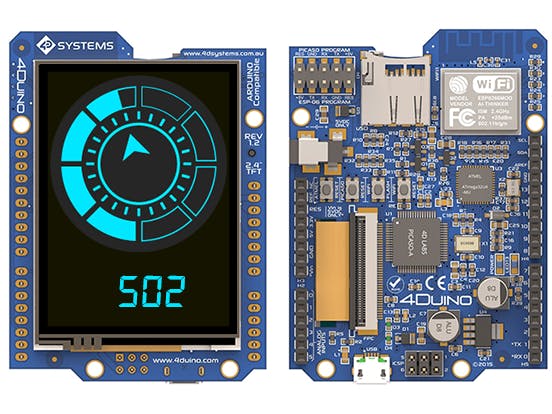
I found this 4Duino module from 4D Systems, for $79, and it comes with a 2.4" LCD, Arduino Leonardo, ESP8266 wireless module, and the Picaso graphics controller. The display is mounted on the backside of the PCB.
Although the display is small, it's more than adequate to display my radial gauge.
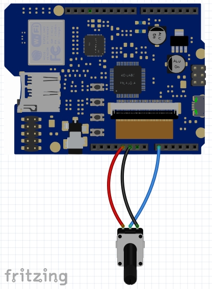
I only needed 3 wires to connect the POT to the 4Duino and that was it.
After installing and launching the Workshop 4 IDE, you'll be greeted by this screen:
You'll be given a choice to "Create a new Project" using no settings or "Create a new Project" and load the previous project's settings. Just choose the no settings one.
A choice of displays will appear:
Choose 4Duino at the top. And an image of the 4Duino module appears on the right, where you can choose the display profile, landscape or portrait.
Choose Portrait and click on Next. Now you're given another choice for Basic Graphics or Extended Graphics:
Since we'll be importing our own images, click on the Extended Graphics option. Now you will reach the main IDE screen:
You'll see a lot of source code already written, but you can ignore most of it and just leave it alone. I ignored all this as most of it dealt with the display initialization.
Step 1: Place your display elementsNext to the File tab there should be a row of other tabs. But for some reason on my system, none of the other tabs appeared, however when I mouseover where the tab should be, it did appear. This must be controlled on a setting somewhere. Anyway, go ahead and mouse over to Widgets, select the System/Media tab.
Click and drag the right most icon, which is called User Images, all the way to the right onto the picture of the 4Duino. You will see a placeholder appear on the screen represented by a red doted line box.
Now it's time to place the images into the placeholder. Click on the Images property field, then click on the... icon on the right of the Images field, as shown below.
A dialog box will appear where you can add all your images. After you select all 24 of the images, your screen will look like this:
Now the code can be added automatically by clicking Paste Static Code.
A few lines are automatically added to your code. At the end of void setup() section:
Display.img_Show(hndl,iUserimages1);
// Userimages1 show initialy, if required
And in the void loop() section:
Display.img_SetWord(hndl, iUserimages1, IMAGE_INDEX, frame);  // frame is 0 to 23
Display.img_Show(hndl,iUserimages1) ;                         // Userimages1
// put your main code here, to run repeatedly:
The important variable here is frame. Frame determines which of the 24 images gets displayed. So the POT value needs to be read and then mapped into a number from 0 to 23. No big deal, as Arduino already has a map function. Taking the code from the Basic Arduino example, called, "AnalogReadSerial", it was easy to figure out how to edit the code:
void loop() {
 word potValue = analogRead(0);
 potValue = map(potValue, 0, 1023, 0, 23);
 Display.img_SetWord(hndl, iUserimages1, IMAGE_INDEX, potValue) ;       //IMAGE_INDEX
 Display.img_Show(hndl, iUserimages1) ;
 delay(100);
}
Code is very simple. First you do an analogRead, then map the value, then show the corresponding image. Then you wait 100ms and loop back and do it all over again.
Now, it's time to place the numeric field which will display the POT value. You go back up to the Widgets tab, choose Digits.
Click and drag the far left icon onto the picture of the display under the radial gauge. What you will see is this:
There are a few things that need changing. We will have to change color, remove decimal point, and remove the leading zeros. To change the color, you have to expand the Palette selection.
Click on dLime and change the RGB value to: Red: 0; Green: 231; Blue: 255.
Click on the Decimals property and change the value from 2 to 0.
Click on LeadingZero property and change yes to no.
Just like with the circular gauge, go ahead and click Paste Static Code.
A few lines get added to your code. At the end of void setup() section:
Display.img_Show(hndl, iLeddigits1);
// Leddigits1 show all digits at 0, only do this once
And in the void loop() section:
LedDigitsDisplaySigned(Display, hndl, numx, iLeddigits1+1, 57, 4, 3, 30, 0) ;
// Leddigits1
The important variable here is numx. This variable will reflect the value of the POT. So it's important where in the code you place this line. Do you want to display the potValue before or after the map function? Answer is before, because displaying a value between 0 and 23 doesn't make sense. So.....
void loop() {
 word potValue = analogRead(0);
 LedDigitsDisplaySigned(Display, hndl, potValue, iLeddigits1+1, 68, 4, 1, 29, 1) ;
// Leddigits1
 potValue = map(potValue, 0, 1023, 0, 23);
 Display.img_SetWord(hndl, iUserimages1, IMAGE_INDEX, potValue) ;
 //IMAGE_INDEX
 Display.img_Show(hndl, iUserimages1) ;
 delay(100);
}
The Workshop 4 IDE requires the Arduino IDE to be installed, as it's needed to compile your Arduino sketch. But you do not need to launch the Arduino IDE or modify any part of the Arduino IDE.
Since we are using custom images, we need to get them onto the µSD card. First install µSD card into your PC. If your PC doesn't have a slot for the card, you will need to get a USB to µSD card reader.
Then go to the Comms tab and select the port that the 4Duino is connected. There is an Arduino Comms setting, but I couldn't figure out what it's used for.
If you only set the Arduino Comms, without setting Comms, you get the below message when you try to compile.
Go back to the Home tab and click on Comp'nLoad all the way to the right on the menu bar.
The following dialog box will appear:
You need to select the correct drive for your µSD card and click OK.
After the files get copied over, your source code will compile and get loaded to the 4Duino. The 4Duino will automatically reset, and oops, the screen will show a flashing green message, "Drive not mounted...."
So take the uSD card out of your PC and put it into the µSD slot on the 4Duino.
And that's it! You have a nifty looking radial gauge to reflect the POT value.


Comments
Please log in or sign up to comment.