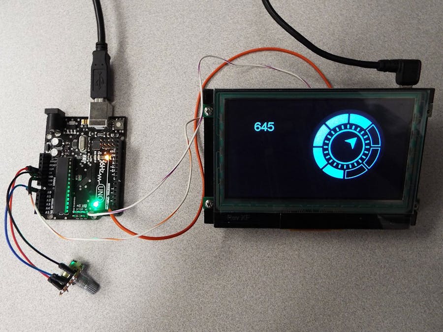
Everybody is familiar with the basic Arduino example of connecting a POT and displaying the value in the serial monitor. You connect one of the leads to one of the Arduino analog pins. Write basically two lines of Arduino code in the loop:
int sensorValue = analogRead(A0);
Serial.println(sensorValue);
And you are done.
I wanted to find a nice graphical way of showing the value using an LCD display without dealing with graphic libraries, or graphic primitives. I definitely didn't want to learn a serial communication protocol. I've gone through all the basic examples for Arduino and like the simplicity of the single loop, and the availability of all the libraries. So with just this knowledge, I wanted to be able to show a visually pleasing way to display the POT value.
I happen to come across the below image on the internet, and thought about what would it take to create this type of indicator for the POT.
This image can be found at www.trashedgraphics.com.
The artist graciously allows his artwork on the site to be freely used.
SoftwareThe easiest method to communicate data between Arduino and any LCD display, can be found with the Amulet Technologies' Arduino library. Amulet has cleverly taken out the need to know their communication protocol or any type of serial communication. The library and instructions for installing the library can be found on GitHub. They've reduced the serial communication implementation down to a simple variable assignment. All it takes to get the POT value and communicate this to the Amulet display via the serial port is one line:
AmuletWords[0] = analogRead(0);
The library "magically" takes the value in AmuletWords[0] and communicates to the Amulet display and the display makes their own variable assignment equating to Amulet:uart1.word(0).value()= AmuletWords[0].
In the Arduino sketch you also need to have something called a serialEvent,
void serialEvent(){
    myModule.serialEvent();
}
The serialEvent gets called at the end of every loop cycle, but does not lie within the loop. If data is on the serial bus, this event gets triggered.
Now on the Amulet display side, you can display whatever you'd like using the variable Amulet:uart1.word(0).value(). Actually programming is a misnomer when it comes to developing an Amulet displays. You will see why in the next section.
Their free trial demo which can be downloaded from their website, is sufficient for most Arduino projects. In the Amulet software environment you don't really type code, as much as you use the mouse to click on different settings. The Amulet display has it's own microcontroller, running it's own RTOS, running it's own firmware developed with their own IDE. This allows for what they've done in simplifying serial communication, to do similar things with developing a GUI. They abstract out the complexity.
Since mouse clicks are hard to describe, here is a video showing the creation of this GUI using GEMstudio. Found at:
But basically these are the steps within GEMstudio:
- Create a new project
- Set background color to black
- Add an Image Sequence Widget
- Import your images for the Image Sequence
- Set min and max values
The most time consuming part of this project was creating the 24 images used for the indicator.
The wire connection between Arduino and the Amulet display is 3 wires.
- The TX pin (Arduino) connected to PIN 15 (UART1_RXD on Amulet header).
- The RX pin (Arduino) is connected to PIN 16 (UART1_TXD on Amulet header).
- And GND pin (Arduino) is conneced to PIN 4 (GND on Amulet header).


_ztBMuBhMHo.jpg?auto=compress%2Cformat&w=48&h=48&fit=fill&bg=ffffff)


Comments
Please log in or sign up to comment.