


Hardware components | ||||||
_ztBMuBhMHo.jpg?auto=compress%2Cformat&w=48&h=48&fit=fill&bg=ffffff) |
| × | 1 | |||
 |
| × | 1 | |||
Software apps and online services | ||||||
 |
| |||||
Hand tools and fabrication machines | ||||||
 |
| |||||
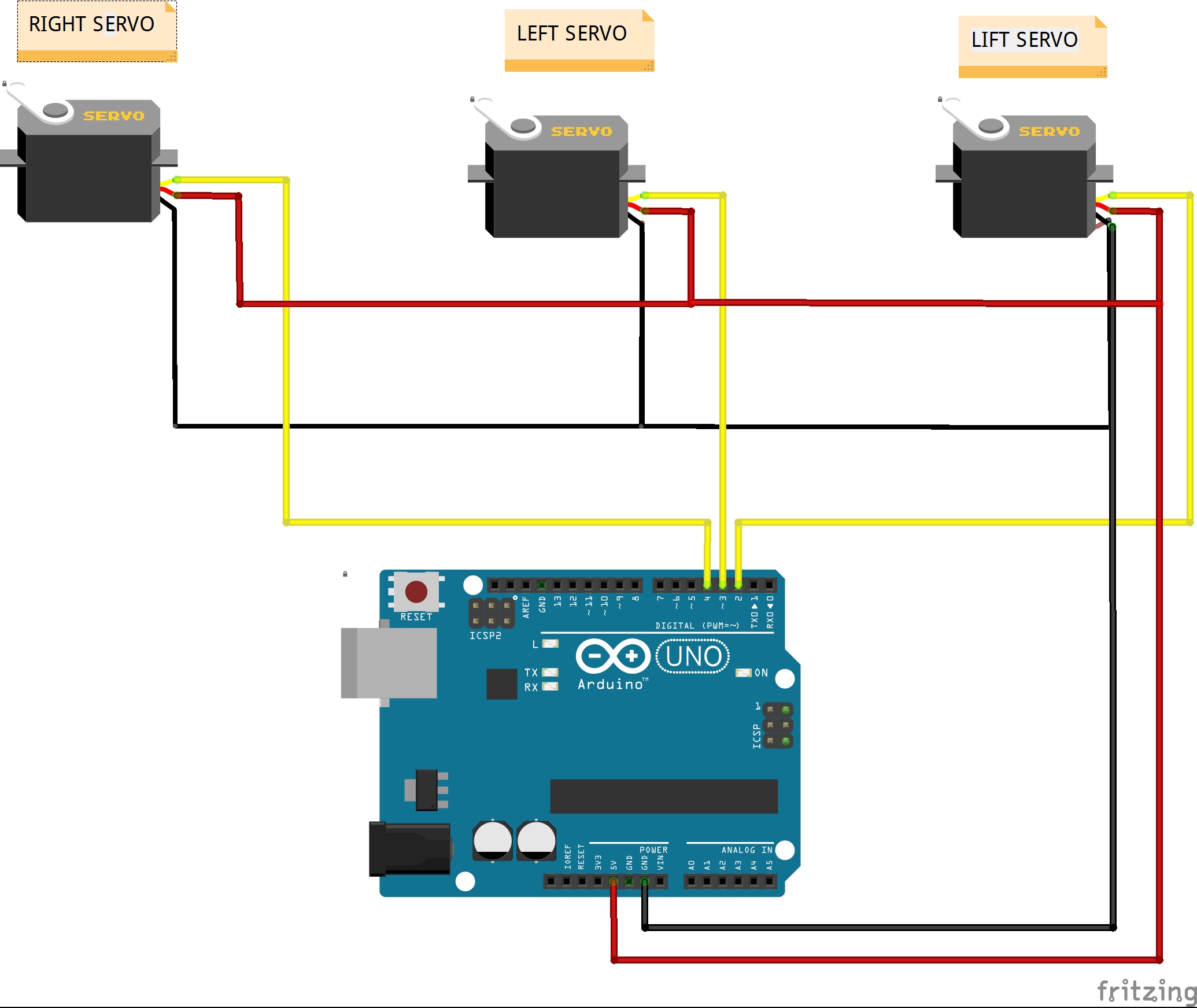
Brilliant idea by Johannes Heberlein that make these robot. Since I do not own a 3D printer or a laser cutter, I decided to create this robot from 3mm PVC pboard cutted with modelers knife.This is the first version of the "yoo" and consists of only Arduino and three servo motors, presented on the Thingiverse page:
https://www.thingiverse.com/thing:248009
There is a lot of different versions and modifications to this clock after that. The minimum settings that should be made for the correct operation of the clock are described in the comments on the code itself. As seen on the video, making a replica of this robot is very simple, even with the most basic knowledge of microcontroller or electronics, but the visual effect and the satisfaction of the finished device are great.
A detailed description of the clock function and build can be found on:
https://wiki.fablab-nuernberg.de/w/Ding:Plotclock
As well as on GitHub:
https://github.com/9a/plotclock
I hope you enjoy doing this "mechanical" clock.
// Plotclock
// cc - by Johannes Heberlein 2014
// v 1.02
// thingiverse.com/joo   wiki.fablab-nuernberg.de
// units: mm; microseconds; radians
// origin: bottom left of drawing surface
// time library see http://playground.arduino.cc/Code/time
// RTC  library see http://playground.arduino.cc/Code/time
//               or http://www.pjrc.com/teensy/td_libs_DS1307RTC.html
// Change log:
// 1.01  Release by joo at https://github.com/9a/plotclock
// 1.02  Additional features implemented by Dave:
//       - added ability to calibrate servofaktor seperately for left and right servos
//       - added code to support DS1307, DS1337 and DS3231 real time clock chips
//       - see http://www.pjrc.com/teensy/td_libs_DS1307RTC.html for how to hook up the real time clock

// delete or mark the next line as comment if you don't need these
#define CALIBRATION      // enable calibration mode
//#define REALTIMECLOCK    // enable real time clock

// When in calibration mode, adjust the following factor until the servos move exactly 90 degrees
#define SERVOFAKTORLEFT 650
#define SERVOFAKTORRIGHT 650

// Zero-position of left and right servo
// When in calibration mode, adjust the NULL-values so that the servo arms are at all times parallel
// either to the X or Y axis
#define SERVOLEFTNULL 2250
#define SERVORIGHTNULL 920

#define SERVOPINLIFT  2
#define SERVOPINLEFT  3
#define SERVOPINRIGHT 4

// lift positions of lifting servo
#define LIFT0 1080 // on drawing surface
#define LIFT1 925  // between numbers
#define LIFT2 725  // going towards sweeper

// speed of liftimg arm, higher is slower
#define LIFTSPEED 1500

// length of arms
#define L1 35
#define L2 55.1
#define L3 13.2

// origin points of left and right servo
#define O1X 22
#define O1Y -25
#define O2X 47
#define O2Y -25

#include <Time.h> // see http://playground.arduino.cc/Code/time
#include <Servo.h>

#ifdef REALTIMECLOCK
// for instructions on how to hook up a real time clock,
// see here -> http://www.pjrc.com/teensy/td_libs_DS1307RTC.html
// DS1307RTC works with the DS1307, DS1337 and DS3231 real time clock chips.
// Please run the SetTime example to initialize the time on new RTC chips and begin running.

  #include <Wire.h>
  #include <DS1307RTC.h> // see http://playground.arduino.cc/Code/time
#endif

int servoLift = 1500;

Servo servo1;  //
Servo servo2;  //
Servo servo3;  //

volatile double lastX = 75;
volatile double lastY = 47.5;

int last_min = 0;

void setup()
{
#ifdef REALTIMECLOCK
  Serial.begin(9600);
  //while (!Serial) { ; } // wait for serial port to connect. Needed for Leonardo only

  // Set current time only the first to values, hh,mm are needed
  tmElements_t tm;
  if (RTC.read(tm))
  {
    setTime(tm.Hour,tm.Minute,tm.Second,tm.Day,tm.Month,tm.Year);
    Serial.println("DS1307 time is set OK.");
  }
  else
  {
    if (RTC.chipPresent())
    {
      Serial.println("DS1307 is stopped.  Please run the SetTime example to initialize the time and begin running.");
    }
    else
    {
      Serial.println("DS1307 read error!  Please check the circuitry.");
    }
    // Set current time only the first to values, hh,mm are needed
    setTime(19,38,0,0,0,0);
  }
#else
  // Set current time only the first to values, hh,mm are needed
  setTime(19,38,0,0,0,0);
#endif

  drawTo(75.2, 47);
  lift(0);
  servo1.attach(SERVOPINLIFT);  //  lifting servo
  servo2.attach(SERVOPINLEFT);  //  left servo
  servo3.attach(SERVOPINRIGHT);  //  right servo
  delay(1000);

}

void loop()
{

#ifdef CALIBRATION

  // Servohorns will have 90° between movements, parallel to x and y axis
  drawTo(-3, 29.2);
  delay(500);
  drawTo(74.1, 28);
  delay(500);

#else


  int i = 0;
  if (last_min != minute()) {

    if (!servo1.attached()) servo1.attach(SERVOPINLIFT);
    if (!servo2.attached()) servo2.attach(SERVOPINLEFT);
    if (!servo3.attached()) servo3.attach(SERVOPINRIGHT);

    lift(0);

    hour();
    while ((i+1)*10 <= hour())
    {
      i++;
    }

    number(3, 3, 111, 1);
    number(5, 25, i, 0.9);
    number(19, 25, (hour()-i*10), 0.9);
    number(28, 25, 11, 0.9);

    i=0;
    while ((i+1)*10 <= minute())
    {
      i++;
    }
    number(34, 25, i, 0.9);
    number(48, 25, (minute()-i*10), 0.9);
    lift(2);
    drawTo(74.2, 47.5);
    lift(1);
    last_min = minute();

    servo1.detach();
    servo2.detach();
    servo3.detach();
  }

#endif

}

// Writing numeral with bx by being the bottom left originpoint. Scale 1 equals a 20 mm high font.
// The structure follows this principle: move to first startpoint of the numeral, lift down, draw numeral, lift up
void number(float bx, float by, int num, float scale) {

  switch (num) {

  case 0:
    drawTo(bx + 12 * scale, by + 6 * scale);
    lift(0);
    bogenGZS(bx + 7 * scale, by + 10 * scale, 10 * scale, -0.8, 6.7, 0.5);
    lift(1);
    break;
  case 1:

    drawTo(bx + 3 * scale, by + 15 * scale);
    lift(0);
    drawTo(bx + 10 * scale, by + 20 * scale);
    drawTo(bx + 10 * scale, by + 0 * scale);
    lift(1);
    break;
  case 2:
    drawTo(bx + 2 * scale, by + 12 * scale);
    lift(0);
    bogenUZS(bx + 8 * scale, by + 14 * scale, 6 * scale, 3, -0.8, 1);
    drawTo(bx + 1 * scale, by + 0 * scale);
    drawTo(bx + 12 * scale, by + 0 * scale);
    lift(1);
    break;
  case 3:
    drawTo(bx + 2 * scale, by + 17 * scale);
    lift(0);
    bogenUZS(bx + 5 * scale, by + 15 * scale, 5 * scale, 3, -2, 1);
    bogenUZS(bx + 5 * scale, by + 5 * scale, 5 * scale, 1.57, -3, 1);
    lift(1);
    break;
  case 4:
    drawTo(bx + 10 * scale, by + 0 * scale);
    lift(0);
    drawTo(bx + 10 * scale, by + 20 * scale);
    drawTo(bx + 2 * scale, by + 6 * scale);
    drawTo(bx + 12 * scale, by + 6 * scale);
    lift(1);
    break;
  case 5:
    drawTo(bx + 2 * scale, by + 5 * scale);
    lift(0);
    bogenGZS(bx + 5 * scale, by + 6 * scale, 6 * scale, -2.5, 2, 1);
    drawTo(bx + 5 * scale, by + 20 * scale);
    drawTo(bx + 12 * scale, by + 20 * scale);
    lift(1);
    break;
  case 6:
    drawTo(bx + 2 * scale, by + 10 * scale);
    lift(0);
    bogenUZS(bx + 7 * scale, by + 6 * scale, 6 * scale, 2, -4.4, 1);
    drawTo(bx + 11 * scale, by + 20 * scale);
    lift(1);
    break;
  case 7:
    drawTo(bx + 2 * scale, by + 20 * scale);
    lift(0);
    drawTo(bx + 12 * scale, by + 20 * scale);
    drawTo(bx + 2 * scale, by + 0);
    lift(1);
    break;
  case 8:
    drawTo(bx + 5 * scale, by + 10 * scale);
    lift(0);
    bogenUZS(bx + 5 * scale, by + 15 * scale, 5 * scale, 4.7, -1.6, 1);
    bogenGZS(bx + 5 * scale, by + 5 * scale, 5 * scale, -4.7, 2, 1);
    lift(1);
    break;

  case 9:
    drawTo(bx + 9 * scale, by + 11 * scale);
    lift(0);
    bogenUZS(bx + 7 * scale, by + 15 * scale, 5 * scale, 4, -0.5, 1);
    drawTo(bx + 5 * scale, by + 0);
    lift(1);
    break;

  case 111:

    lift(0);
    drawTo(70, 46);
    drawTo(65, 43);

    drawTo(65, 49);
    drawTo(5, 49);
    drawTo(5, 45);
    drawTo(65, 45);
    drawTo(65, 40);

    drawTo(5, 40);
    drawTo(5, 35);
    drawTo(65, 35);
    drawTo(65, 30);

    drawTo(5, 30);
    drawTo(5, 25);
    drawTo(65, 25);
    drawTo(65, 20);

    drawTo(5, 20);
    drawTo(60, 44);

    drawTo(75.2, 47);
    lift(2);

    break;

  case 11:
    drawTo(bx + 5 * scale, by + 15 * scale);
    lift(0);
    bogenGZS(bx + 5 * scale, by + 15 * scale, 0.1 * scale, 1, -1, 1);
    lift(1);
    drawTo(bx + 5 * scale, by + 5 * scale);
    lift(0);
    bogenGZS(bx + 5 * scale, by + 5 * scale, 0.1 * scale, 1, -1, 1);
    lift(1);
    break;

  }
}


void lift(char lift) {
  switch (lift) {
    // room to optimize  !

  case 0: //850

      if (servoLift >= LIFT0) {
      while (servoLift >= LIFT0)
      {
        servoLift--;
        servo1.writeMicroseconds(servoLift);
        delayMicroseconds(LIFTSPEED);
      }
    }
    else {
      while (servoLift <= LIFT0) {
        servoLift++;
        servo1.writeMicroseconds(servoLift);
        delayMicroseconds(LIFTSPEED);

      }

    }

    break;

  case 1: //150

    if (servoLift >= LIFT1) {
      while (servoLift >= LIFT1) {
        servoLift--;
        servo1.writeMicroseconds(servoLift);
        delayMicroseconds(LIFTSPEED);

      }
    }
    else {
      while (servoLift <= LIFT1) {
        servoLift++;
        servo1.writeMicroseconds(servoLift);
        delayMicroseconds(LIFTSPEED);
      }

    }

    break;

  case 2:

    if (servoLift >= LIFT2) {
      while (servoLift >= LIFT2) {
        servoLift--;
        servo1.writeMicroseconds(servoLift);
        delayMicroseconds(LIFTSPEED);
      }
    }
    else {
      while (servoLift <= LIFT2) {
        servoLift++;
        servo1.writeMicroseconds(servoLift);
        delayMicroseconds(LIFTSPEED);
      }
    }
    break;
  }
}


void bogenUZS(float bx, float by, float radius, int start, int ende, float sqee) {
  float inkr = -0.05;
  float count = 0;

  do {
    drawTo(sqee * radius * cos(start + count) + bx,
    radius * sin(start + count) + by);
    count += inkr;
  }
  while ((start + count) > ende);

}

void bogenGZS(float bx, float by, float radius, int start, int ende, float sqee) {
  float inkr = 0.05;
  float count = 0;

  do {
    drawTo(sqee * radius * cos(start + count) + bx,
    radius * sin(start + count) + by);
    count += inkr;
  }
  while ((start + count) <= ende);
}


void drawTo(double pX, double pY) {
  double dx, dy, c;
  int i;

  // dx dy of new point
  dx = pX - lastX;
  dy = pY - lastY;
  //path lenght in mm, times 4 equals 4 steps per mm
  c = floor(4 * sqrt(dx * dx + dy * dy));

  if (c < 1) c = 1;

  for (i = 0; i <= c; i++) {
    // draw line point by point
    set_XY(lastX + (i * dx / c), lastY + (i * dy / c));

  }

  lastX = pX;
  lastY = pY;
}

double return_angle(double a, double b, double c) {
  // cosine rule for angle between c and a
  return acos((a * a + c * c - b * b) / (2 * a * c));
}

void set_XY(double Tx, double Ty)
{
  delay(1);
  double dx, dy, c, a1, a2, Hx, Hy;

  // calculate triangle between pen, servoLeft and arm joint
  // cartesian dx/dy
  dx = Tx - O1X;
  dy = Ty - O1Y;

  // polar lemgth (c) and angle (a1)
  c = sqrt(dx * dx + dy * dy); //
  a1 = atan2(dy, dx); //
  a2 = return_angle(L1, L2, c);

  servo2.writeMicroseconds(floor(((a2 + a1 - M_PI) * SERVOFAKTORLEFT) + SERVOLEFTNULL));

  // calculate joinr arm point for triangle of the right servo arm
  a2 = return_angle(L2, L1, c);
  Hx = Tx + L3 * cos((a1 - a2 + 0.621) + M_PI); //36,5°
  Hy = Ty + L3 * sin((a1 - a2 + 0.621) + M_PI);

  // calculate triangle between pen joint, servoRight and arm joint
  dx = Hx - O2X;
  dy = Hy - O2Y;

  c = sqrt(dx * dx + dy * dy);
  a1 = atan2(dy, dx);
  a2 = return_angle(L1, (L2 - L3), c);

  servo3.writeMicroseconds(floor(((a1 - a2) * SERVOFAKTORRIGHT) + SERVORIGHTNULL));

}

Comments
Please log in or sign up to comment.