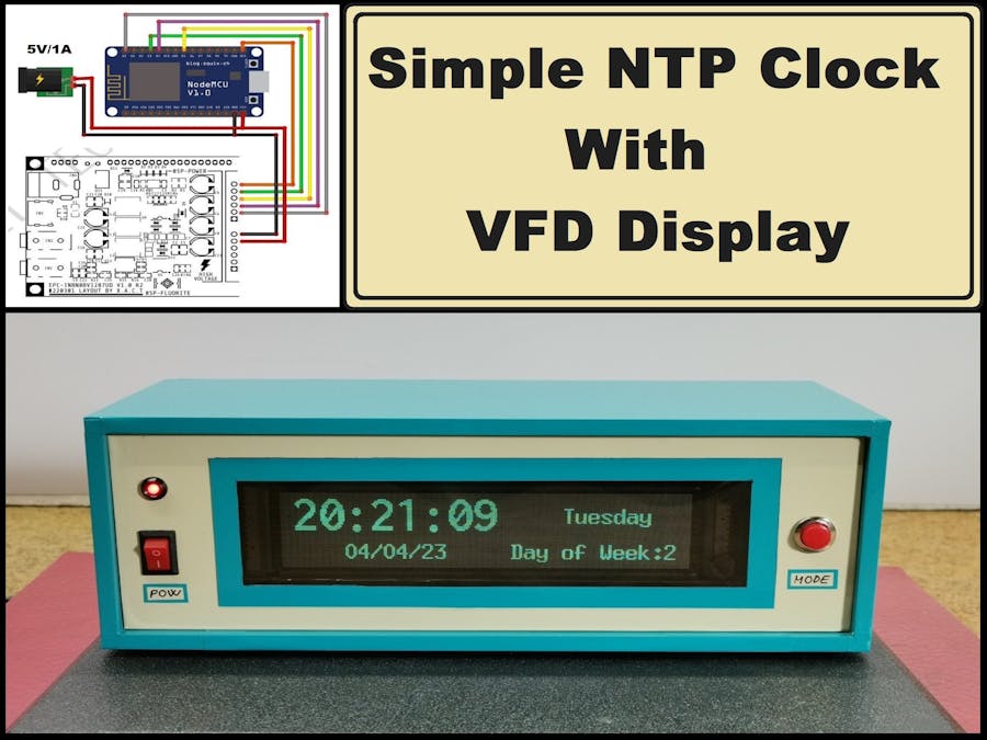
A VFD (Vacuum Fluorescent Display) is an electronic display device that is commonly used for displaying numeric or alphanumeric characters. It is similar to an LCD (Liquid Crystal Display) but uses a different technology to display information. VFD displays are known for their high brightness, high contrast, and wide viewing angle, making them suitable for use in a variety of applications, including digital clocks. Exactly such a clock is described in this video.
I recently acquired a VFD display with a resolution of 256 x 50 dots for a relatively affordable price.
Unfortunately, I could not get a datasheet or any more detailed information from the supplier, except that it is compatible with an STM32 microcontroller, which for me meant that it can be easily connected to other microcontrollers such as Arduino. On the back of the PCB, the display model is marked as GP1287, so based on this information I found a document that shows the pinout of the display and some basic data. However, to create code without the support of libraries is relatively complex.
For that reason, I looked in more detail at the libraries for graphic support of displays, when I discovered that the latest versions of the U8G2 library support exactly this type of VFD display. Now with this kind of support it is quite easy to create code that will use this display. To demonstrate these claims, as the simplest example, I decided to create an NTP clock that retrieves the correct time over the Internet.
Making such a clock is extremely simple and consists of only two components:
- ESP8266 microcontroller board
- and GP1287 VFD display
First I will test the device with a short demo sketch that is an integral part of the library, which demonstrates some of the graphical capabilities
In the code, we only need to enter the credentials of the local Wi-Fi network, and then upload it to the microcontroller. As for this procedure, this time we will not hold back, because it has been described several times in my previous projects, and there are also excellent tutorials on the Internet.
After turning on the device, we need to wait for a certain time while the microcontroller connects to the Wi-Fi network and NTP servers. As seen on the screen, the correct time appears with the largest digits, the date is displayed below it, in the upper right part of the screen there is numerical information about the day of the week, and below it the day of the week.
As I mentioned before, the information on the display is clearly visible from all angles thanks to the specific way of radiating light, both in daylight and at night.
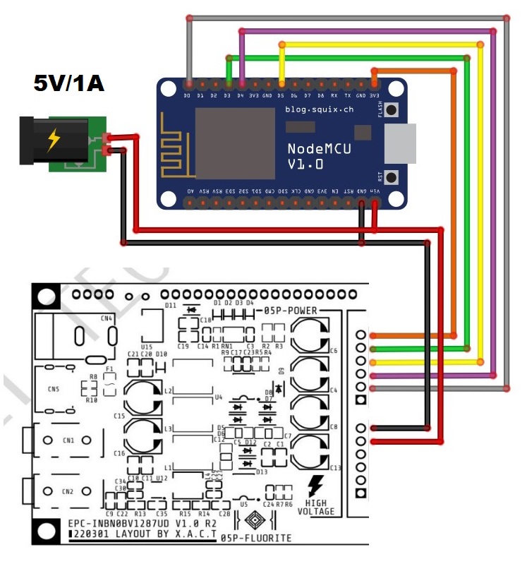
This is the simplest example that basically shows how to connect the display to an ESP8266 microcontroller, but it can be connected to an Arduino in a similar way by changing the number of pins when defining it in the U82G library.
Finally, the device is installed in a suitable box made of PVC material with a thickness of 5 mm and covered with colored self-adhesive wallpaper.
Update:
Due to the relatively high consumption of the display, it is preferable to power it through the power connector of the display itself, which is shown in the picture.


Comments
Please log in or sign up to comment.