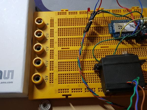
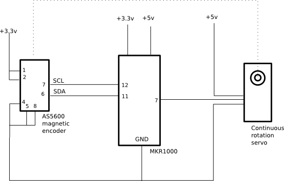
Many position control use steppers because they are easy to deal with and are cheap. RC servos are easy and cheap too, but they are limited to half revolution. Continuous rotation servos can do more than half revolution but we cannot control position. This projects adds an inexpensive magnetic encoder that fits inside the servo to add the position sensing.
That means a single revolution now consists of 4096 steps or discrete angles, but any desired value of turns or steps can be achieved. Just remember these servos are not going to win any speed race.
But to make the project a bit more interesting for many of us, the use of the MKR1000 allows us to allow the control to happen wirelessly too.
I have a set of commands that are available both to USB communication or to UDP communication via WiFi. That means you can learn and test how it works connected to your computer USB and later you can move the module to another location and be accessed wirelessly.
For wireless communication I am using UDP protocol and port 23. The device IP address is reported to the serial terminal at the beginning so you can learn what IP is the board going to use. Please remember to insert in the source code two important values: your wifi network name (SSID) and password.
There is a really small circuit that can be done at a small SOIC-8 adapter board to be inserted inside the guts of the servo.
Some changes were needed for the continuous rotation to accept the magnetic encoder, so I had to design and print a part to hold the magnet attached to the output shaft. You can see below a bit of the process of adding the encoder to the servo.
For accessing the controller wirelessly we need to know the IP address of it first, and for that we will need to use the Arduino IDE serial monitor:
Once we know the IP address to connect to, we can use netcat (or nc) command to connect to the controller and send commands. I used telnet tool before but I realized better performance and stability was obtained using UDP instead.
In the image above three different commands have been issued. The first one 'h' is listing the help of available commands. Next is 'q' that reports the current set of values of PID controller that governs the closed-loop control of the servo motor. And third command '?' reports the position of the output shaft, the controller output and the target location.
I used a continuous rotation servo for this project because it comes with its own power electronics, but this project can be easily adapted to other types of DC motors if you bring in an h-bridge control electronics and make a small change to the control code.
The most interesting command once everything is configured is the 'X' command that allows to send the servo to any desired location. Like X5000 for example will send it to the position 500 that, depending on your setup, will be a certain number of inches. Negative numbers are also allows but that will depend on where you set the zero of your motion platform.


Comments
Please log in or sign up to comment.