Twice, in three months time, the timer for my pool pump failed. This inspired me to create this project. The cost of replacing those timers was over $120 and all I had to show forit was a timer that gave me very little control and a high failurerate. I also suffered a failure of thetemperature sensor on my solar water heater that cost an additional $30.
I knew that I could create a cost-effective automatedpool controller that gave me much more control over when my pool pump ran. I wanted to have more variables as to when the pump ran instead of the simple time and day of the existing timer. I also wanted to be able to not only automatemy pool pump, but also monitor the status of various aspects of my pool environment. A further goal was to be able toaccomplish these tasks from anywhere using any device.
The project I have created is very cost-effective as it utilizesa Raspberry Pi running Windows 10 IoT Core, Relays, Arduino Mini Pro as well astemperature sensors, wiring and 3D printed components. I completed this project for far less moneythan I had paid for the two prior timers and solar temperature sensor.
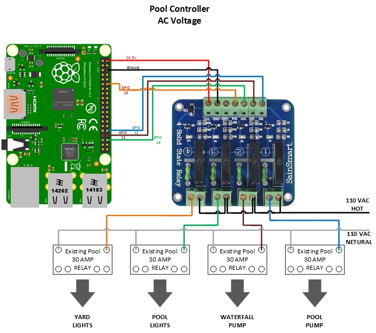
Pool Pump Control (AC Components)I started my project by controlling solid state relays frommy Raspberry Pi running Windows 10 IoT Core. These relays allow meto control my AC (Alternating Current) components such as the pool pump. The solid state relays control the existing 30Amp AC relays that the old timer had utilized. After designing and testing the circuit for the pool pump, I created additional functionality to control other AC components such as my pool waterfall, and my pool and yard lights. With this portion of the project designed, I could control all of these elements remotely. No longer would my family members or I need to physically open the controlbox in order to turn on the waterfall, turn on the pool or yard lights or set the timerfor the pool pump.
My son designed the Pool Controller enclosure and created it using our3D printer and ensured that both the Raspberry Pi and solid state relays hada secure fit within the controller box.
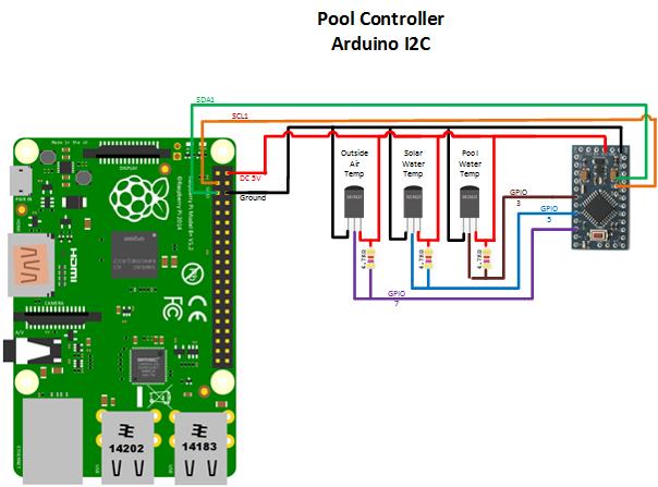
One of the design goals for myproject was to allow control based on variables in addition to Day and Time. I wanted to be able to take into account outside airtemperature as well as solar water heater and pool watertemperatures to determine when the pump should run and when it should be atrest. One example of when this type ofoperation would be crucial is when the outside air temperature is very cold andnear freezing. If the pool watertemperature is also close to freezing I need to ensure my pool and waterfallpumps are running to prevent pipes from freezing and damaging the systems. Using this project I will be able toaccomplish this even when I am not at home. In order to implement this, I incorporated temperature sensors into myproject. I read those sensors utilizing an Arduino Mini Pro which sends thatdata to the same Raspberry Pi that controls the pool and waterfall pumps via I2Cinterface.
Outside Air Temperature SensorThe outside air temperature sensor was the first sensor I incorporated. Again, my son designed and printed the sensor mount on our 3D printer. He tried both PLA and ABS, ABS actually works better as it is more weather resistant and has a higher glass transition temperature making it more heat resistant. Ensure that you print with at least 75% infill. The sensor was connected as described above in the schematic.
I then incorporated the pool water and solar heater temperature sensors. This would allow the project to gather water temperature data that would be displayed to a user as well as provide further variables to determine when certain components ran or were at rest. First, a sensor mount was designed and 3D printed. As mentioned earlier, ABS actually works better due to better weather and heat resistance. Also ensure that you use at least 75% infill.
After printing the Water temperature sensor mount, I used a countersink drill bit to create a 45 degree area around the sensor hole. This would allow the JB Weld to have more surface area to adhere to. I prefered to use a drill bit to do this over changing the 3D print design as the rough cut of the drill bit seemed to give the JB Weld better holding power.
The next step was to insert the temperature sensor into the mount until it extends about 3/4" out of the bottom of the mount. Add the seat washer to hold it into place.
Next, fill the top of the mount with JB Weld and allow 24 hours to dry.
After waiting at least 24 hours for the JB Weld to dry, it was time to install the water temperature sensors.
IMPORTANT Note: Ensure that all pumps are off before attempting to install the water temperature sensors!
After ensuring that all water pumps are off, it is a good idea to open any valves that can remove water pressure from the area you are installing the water temperature sensors in. This will ease installation greatly (and keep you dry as well).
Drill a 5/16" hole in the pool piping. Install the water temperature sensor and utilize 2 clamps to firmly hold it in place. Do not make the same mistake I did and overtighten the clamps, over tightening will crush the sensor mount. Close valves and turn on pumps. Check for leaks.
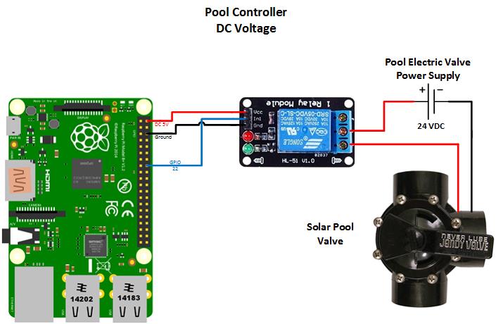
After having the temperature sensors in place, I could then design and install the Solar Water heater valve control. The Solar Heater utilizes DC voltage as opposed to the AC voltages used with the other pool components mentioned earlier. This required me to control a DC relay instead of an AC relay. The concept is similar, but the required relays are different. Ensure that the relays that you use for your project will control the correct type of voltages used by the device you are controlling.
This control allows me to direct pool water up to the Solar panels on my roof. I only want to direct water to the panels when the outside air temperature is above 60 degrees. Once water is being diverted to the panels, ensure that the returning water is at least 2 degrees warmer than the pool water. Otherwise, it is a waste of energy to pump the water to the panels.
The wiring and connections of this control is provided in the Pool Controller DC Components schematic.
Application DevelopmentAfter installing Windows 10IoT Core on my Raspberry Pi, I realized it has a built in web server that is used tomanage it. I wondered if this was a strippeddown version of IIS? If so, I could just writesome restful services on IIS and call them for this project. After many web searches and lots of research, it didn't appear to be possible. That approach would be one that I would prefer, but it doesn't seem feasible at this point in time.
Taking a different approach, I reviewed the example ”Blinky Web Server" and an article on ”Druss Blog”. I decided to build a headless Windows 10 IoT Core Background Application that acts as a simple HTTP Web Server responding to HTTP GET and POST requests.
Within a few days, I had a workingprototype. This gave me a lot of confidence that my project could be successful. So I decided to move forward with this architecture. After thoroughlytesting my code via the Visual Studio 2015 debugger, I was under the impression that I was could easily deploy myapplication.
Deploying the ApplicationThis is a point that I struggled with, so I hope to show you how to avoid such difficulty. Because my Application was thoroughly tested in the Visual Studio 2015 debugger, I was under the impression that I could just change the mode from Debug to Release to deploy my application. I tried this approach and it did in fact deploy my application and start it in Debug mode. I then stopped debug and attempted to run the application from AppX Manager. I had no success when I attempted this, I would just get a generic error that stated, "Application failed to initialize."
The solution to this issue is to delete the current deployment and then install the application from the AppX Manager instead. This cost me a lot of time, so I hope this helps you avoid that issue.
Even though the application ran flawlessly in Visual Studio 2015 debug mode, it would die after receiving the first HTTP request. I spent a lot of time trying to troubleshoot this and still do not know why this occurs.
Feeling pressure to get this project completed, I decided to change my project to be just like the “Blinky Web Server” example. In my implementation, I didn’t see the need for a Windows 10 IoT Core screen application due to the fact that I planned for the web server to control the GPIO pins and read the I2C interface (not a screen application). What I did in my project was to have the screen application start the web server. The Web Server then sends messages back to the screen application so I can see what HTTP call was received by my server. This approach seems to be rock solid and it’s exactly the same code I used in my original attempt.
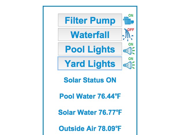
User InterfaceFinally, I built an HTML control program that will run onvirtually any device. This allows me tonot only control the pool pump, waterfall and pool lights, but also monitor theadditional sensors from anywhere.
Later, I utilized OpenHAB and created a site map that gave methis additional interface.
I hope you enjoyed reading about my project as much as I didcreating it. Thank You.
YouTube, Vimeo or Vine link, and press Enter


_3u05Tpwasz.png?auto=compress%2Cformat&w=40&h=40&fit=fillmax&bg=fff&dpr=2)
Comments