/************************************************************************
*
* Test of the Pmod
*
*************************************************************************
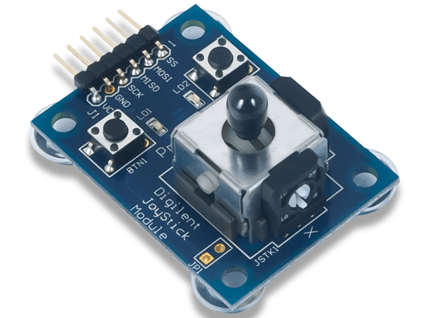
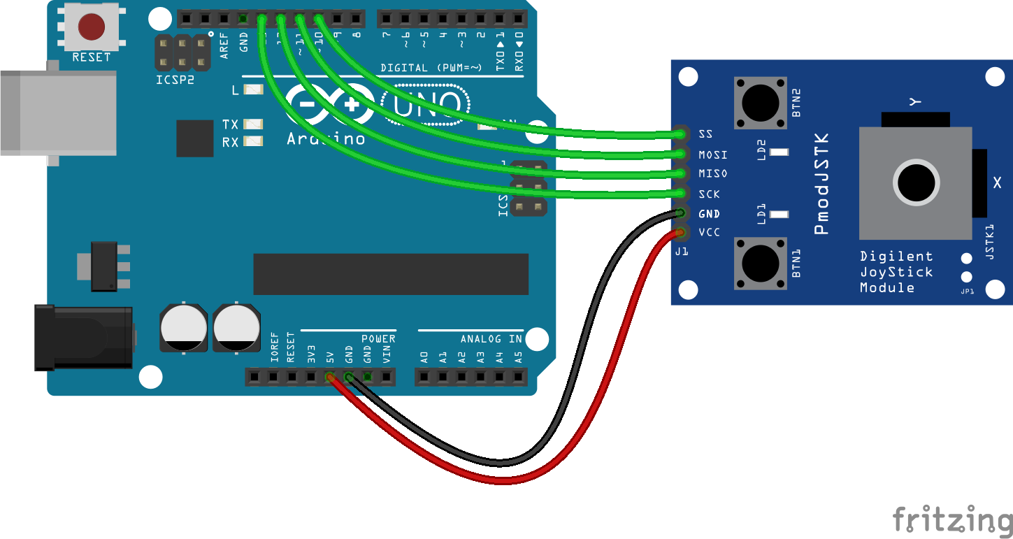
* Description: Pmod_JSTK
* X and Y values will be shown in serial monitor in a table
* and LEDs LD1 and LD2 will light on when
* BTN1 and BTN2 are pushed.
*
*
* Material
* 1. Arduino Uno
* 2. Pmod JSTK
*
************************************************************************/
#define CS 10 // affectation of CS pin
#include <SPI.h> // Include library
int i;
byte recu[6]; // store data from module
int X;
int Y;
int led=128;
void setup()
{
Serial.begin(9600); // initialization of the serial communication
SPI.begin(); // initialization of SPI port
SPI.setDataMode(SPI_MODE0); // configuration SPI link in mode 0
SPI.setClockDivider(SPI_CLOCK_DIV16); // configuration of clock at 1MHz
pinMode(10, OUTPUT);
}
void loop()
{
digitalWrite(CS, LOW); // activation of CS line
delayMicroseconds(15); // see doc: wait 15μs after activation of CS line
for (i=0;i<5;i=i+1)
{
recu[i] = SPI.transfer(led); // Send 5 data to get data from module (LEDs are off)
delayMicroseconds(10); // see doc: wait 10μs after each send
}
digitalWrite(CS, HIGH); // deactivation of CS line
X = recu[0]; // X has a 10-bit format
X |= (recu[1] << 8);
Y = recu[2]; // Y has a 10-bit format
Y |= (recu[3] << 8);
for (i=0;i<5;i=i+1) // write in serial monitor
{
Serial.print("i");
Serial.print(i);
Serial.print("=");
Serial.print(recu[i]);
Serial.print('\t'); // tabulation
}
Serial.print("X=");
Serial.print(X);
Serial.print('\t'); // tabulation
Serial.print("Y=");
Serial.println(Y);
delay(10);
switch (recu[4])
{
case 2: // BTN1 working
led=129;
break;
case 4: // BTN2 working
led=130;
break;
case 6: // BTN1 and BTN2 working
led=131;
break;
default:
led=128;
break;
}
}


_ztBMuBhMHo.jpg?auto=compress%2Cformat&w=48&h=48&fit=fill&bg=ffffff)


Comments
Please log in or sign up to comment.