/************************************************************************
*
* Test of the Pmod
*
*************************************************************************
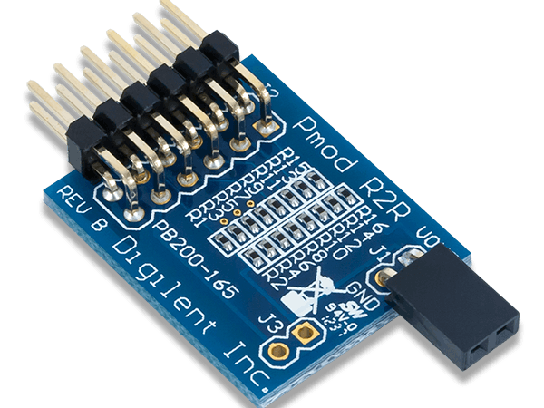
* Description: Pmod_R2R
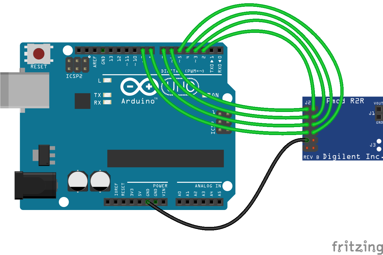
* The output voltage is adjustable according to the logic levels
* applied to pins 2 to 9 of the Arduino.
* The output voltage is the sum of all components.
*
* Material
* 1. Arduino Uno
* 2. Pmod R2R
*
************************************************************************/
void setup()
{
for (int i=2; i<=9; i++) // configuration ofpins 2 to 9 as output
{
pinMode(i,OUTPUT);
}
}
void loop()
{
// Input D7 of the module in the high state imposes a component of VCC/2
digitalWrite(9,HIGH);
// Input D6 of the module in the high state imposes a component of VCC/4
digitalWrite(8,LOW);
// Input D5 of the module in the high state imposes a component of VCC/8
digitalWrite(7,LOW);
// Input D4 of the module in the high state imposes a component of VCC/16
digitalWrite(6,LOW);
// Input D3 of the module in the high state imposes a component of VCC/32
digitalWrite(5,HIGH);
// Input D2 of the module in the high state imposes a component of VCC/64
digitalWrite(4,HIGH);
// Input D1 of the module in the high state imposes a component of VCC/128
digitalWrite(3,HIGH);
// Input D0 of the module in the high state imposes a component of VCC/256
digitalWrite(2,HIGH);
}


_ztBMuBhMHo.jpg?auto=compress%2Cformat&w=48&h=48&fit=fill&bg=ffffff)


Comments
Please log in or sign up to comment.