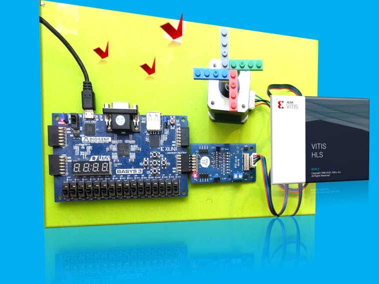
The goal of this mini-project is to drive a 4-phase bipolar stepper motor using high-level synthesis for FPGA. To achieve this goal, here I am going to control the 17HS4401S stepper motor, which is connected to the Basys3 board via a Pmod-Step (Stepper Motor Driver). Two IPs described in HLS are used to rotate the stepper motor. If you are interested in designing with HLS, please refer to here or here.
A Stepper motor is usually used to make electronically controlled precise movements. It has several applications, especially in DVD players, printers, CNC machines, and robotic arms, to name a few.
Like other types of motors, the stepper motor consists of two main parts: stator and rotor. The stator consists of individual sets of coils. In contrast to other types of motors, the rotor in a stepper motor rotates in discrete steps. After each step, the rotor holds itself in position. These discrete steps are controlled by a proper sequence of pulses on the stator coils.
In other words, a stepper motor converts electrical pulses into discrete mechanical movements.
The number of coils will differ based on the type of stepper motor, but for now, it is enough to understand that in a stepper motor, the rotor consists of metal poles, and each pole will be attracted by a set of coils in the stator.
When a coil gets energised, it acts as a magnet, and the rotor pole gets aligned to it. When the rotor rotates to adjust itself to align with the stator, it is called “one step”.
There are mainly three types of stepper motors based on their rotor construction:
Variable reluctance stepper motor: They have an iron core rotor
Permanent magnet stepper motor: They have a permanent magnet rotor
Hybrid synchronous stepper motor: They are a combination of Variable reluctance and permanent magnet stepper motors
We can also classify the stepper motors as Unipolar and Bipolar based on the type of stator coil wiring.
The following figure shows the coil configuration of a 4-wire bipolar stepper motor.
There are four different drive methods for stepper motors:
- One-phase-on stepping or Wave Stepping (Full Step)
- 2-phase-on (Full Step)
- 1&2-phase-on (Half Step)
- Microstep
The simplest case is the one-phase-on
To understand the driving signals that an HLS function should generate, let us simplify the motor structure shown in the following figure. Here, each motor step is 90°, representing 1.8° of the rotor rotations in our actual motor.
To rotate the rotor, we should energise the coils one after another, as shown in the following figure.
When we energise the A phase, it attracts the rotor. We turn off A and turn on B, the rotor rotates 90° (1.8°) and so on. Each time only one phase is energised.
If we assume A–>black, B–>blue, C–>green and D–>red, then the following HLS function can generate the proper signals to rotate the motor continuously. Here, the motor_clk_rate input argument is a 100Hz clock frequency.
typedef enum {s0, s1, s2, s3} stepper_motor_state;
void bipolar_stepper_motor( bool motor_clk_rate, ap_uint<4> &motor_signal) {
#pragma HLS INTERFACE ap_none port=motor_signal
#pragma HLS INTERFACE ap_none port=motor_clk_rate
#pragma HLS INTERFACE ap_ctrl_none port=return
    static stepper_motor_state state=s0;
    stepper_motor_state next_state=state;
    ap_uint<4> motor_signal_tmp;
    switch (state) {
    case s0:
        if (motor_clk_rate == 1) {
            next_state = s1;
        } else {
            next_state = s0;
        }
        motor_signal_tmp = 0b1000;
        break;
    case s1:
        if (motor_clk_rate == 1) {
            next_state = s2;
        } else {
            next_state = s1;
        }
        motor_signal_tmp = 0b0010;
        break;
    case s2:
        if (motor_clk_rate == 1) {
            next_state = s3;
        } else {
            next_state = s2;
        }
        motor_signal_tmp = 0b0100;
        break;
    case s3:
        if (motor_clk_rate == 1) {
            next_state = s0;
        } else {
            next_state = s3;
        }
        motor_signal_tmp = 0b0001;
        break;
    default:
        break;
    }
    state = next_state;
    motor_signal = motor_signal_tmp;
}
The following testbench can be used to test the stepper motor driver design.
int main() {
    int status = 0;
    bool       motor_clk_rate;
    ap_uint<4> motor_signal;
    motor_clk_rate = 0;
    for (int i = 0; i < 20; i++) {
        for (int j = 0; j < 5; j++) {
            bipolar_stepper_motor ( motor_clk_rate, motor_signal);
            motor_clk_rate = 0;
            std::cout << "motor_signal = " << std::setfill ('0') << std::setw (4) << (std::bitset<4>)motor_signal << std::endl;
        }
        motor_clk_rate = 1;
    }
    return status;
}
After running the RTL/C co-simulation in Vitis-HLS, the following waveform illustrates the design timing digram.
The design in Vivado consists of two IPs generated by Vitis-HLS. The first IP generates the 100Hz single-cycle clock pulses and the second IP generates the stepper motor signals.
The stepper motor is connected to the Pmod JC connector on the Basys3 board via Pmod-Step. Therefore, the following constraints define the design port connected to the JC interface.
##Sch name = JC7
set_property PACKAGE_PIN L17 [get_ports {motor_signal[0]}]
set_property IOSTANDARD LVCMOS33 [get_ports {motor_signal[0]}]
#Sch name = JC8
set_property PACKAGE_PIN M19 [get_ports {motor_signal[1]}]
set_property IOSTANDARD LVCMOS33 [get_ports {motor_signal[1]}]
#Sch name = JC9
set_property PACKAGE_PIN P17 [get_ports {motor_signal[2]}]
set_property IOSTANDARD LVCMOS33 [get_ports {motor_signal[2]}]
#Sch name = JC10
set_property PACKAGE_PIN R18 [get_ports {motor_signal[3]}]
set_property IOSTANDARD LVCMOS33 [get_ports {motor_signal[3]}]


Comments
Please log in or sign up to comment.