Like my previous projects, this one also demonstrates that “Designing digital systems with HLS for FPGA is fun”. If you are interested in learning HLS coding techniques please refer here or here.
UART is an old mechanism for serial communication which still is used in several electronic boards and computing platforms. Its implementation in an HDL language is not tricky and can be considered as an undergraduate homework. Here, I am going to take this example and show how easy and fun it is to implement that in HLS.
So, conceptually it is a trivial project; however, it is instructive for people who are interested in HLS.
Now the project definition: The following figure shows the simple structure of the project.
Our design in the FPGA receives an 8-bit data and whenever the push-button is pressed sends that to a computer to be shown in a serial terminal.
The eight slid-switches on the Basys3 board is used to enter a byte of data (for example an ASCII code of a letter or symbol). Also, the UP push-button is used as the send control key.
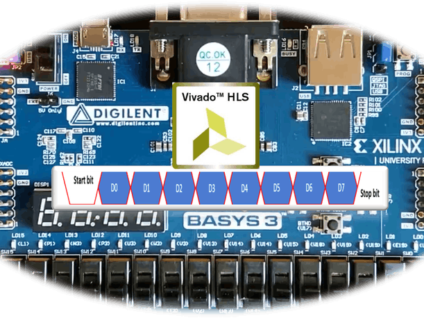
The design is straightforward, and it should receive the data, and then should add a “0” start bit and a “1” Stop bit to that, finally it should send that out with the baud rate of 9600 bit/s.
As the Basys3 board has a 100MHz clock signal, a simple for-loop can be used to generate the baud rate clock signal.
bool delay(long long int n) {
  static bool dummy = 0;
  for (long long int j = 0; j < n; j++) {
#pragma HLS pipeline
    dummy = !dummy;
  }
  return dummy;
}
void uart_baudrate_clock(bool &baudrate_clk) {
  static bool s = 0;
  s=!s;
  baudrate_clk = s;
  delay(5208);
}
After generating the board-rate clock, a simple state machine can send the data out.
void uart_data_transfer(bool &uart_tx, ap_uint<8> data, bool baud_rate_clock, bool start) {
  static bool send_bit = 1;
  static bool start_state = 0;
  static bool transfer = 0;
  static unsigned int count = 0;
  static int state = 0;
  ap_uint<10> d= ((bool)0b1, (ap_int<8>)data, (bool)0b0);
  if (start == 1 && start_state == 0) {
    transfer = 1;
    start_state = 1;
    count = 0;
  }
  if (start == 0 && start_state == 1) {
    start_state = 0;
  }
  if (baud_rate_clock == 1 && state == 0 && transfer == 1) {
    send_bit = d[count++];
    if (count == 10) {
      transfer = 0;
    }
    state = 1;
  }
  if (baud_rate_clock == 0 && state == 1) {
    state = 0;
  }
  uart_tx = send_bit;
}
After synthesising these codes into RTL modules, we can create the Vivado project and generate the FPGA bit-stream.
Now we can check the design on the board.


Comments
Please log in or sign up to comment.