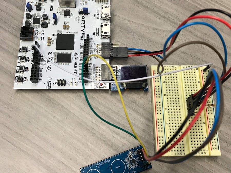
This project represents the control of an FPGA from Linux user-space. This project utilizes a Digilent PmodOLED_RGB and a Digilent PmodCDC1, as well as the available inputs and outputs on the ArtyZ7-20 board.
The ArtyZ7-20 contains a Xilinx Zynq chip which contains a 650Mhz ARM dual-core processor as well as some FPGA fabric. An FPGA design can be instantiated using Xilinx Vivado. Additionally, using Xilinx Petalinux, a Linux kernel and root file-system can be obtained for the ARM processor. This allows us to run the Linux operating system, but still use the functionality of the FPGA. FPGA configurations can be loaded and changed dynamically without interrupting or crashing the running kernel.
I decided to make a generic configuration of hardware in the FPGA that I could use to interface with the most common peripherals without having to change my block design continuously.
The hardware partsThis block design contains the following hardware instantiated in the FPGA:
- 2 I2C Controllers
- 2 SPI Controllers
- 2 UART Controllers
- 1 PWM Controller with 6 channels
- 40 GPIO channels
However, this specific project uses only one I2C controller, one SPI controller, the PWM controller, and 10 GPIO channels. They are connected as follows:
- i2c-sda connected to JA pin 4
- i2c-scl connected to JA pin 3
- spi-cs connected to JB, pin 1
- spi-MOSI connected to JB, pin 2
- spi-MISO connected to JB, pin 3
- spi-sclk connected to JB, pin 4
- PWM channels 0 through 5 are connected to the BGR leds on the Arty Z7
- GPIO channels 0 through 3 are connected to LD[0:3] on the Arty Z7
- GPIO channels 4 through 7 are connected to JB pins 7 through 10
- GPIO channels 8 through 11 are connected to BTN[0:3] on the Arty Z7
- GPIO channels 12 and 13 are connected to SW[0:1] on the Arty Z7
The PmodOledRGB plugs directly into the JB port on the ArtyZ7. A breadboard will be required to interface with the PmodCDC1, though, as the use of I2C required pull-up resistors that must be added. I used pull-up resistors of value 4.7K, which is pretty standard. Please reference the schematic below to see how to connect the pull-up resistors.
Additionally, I wrote a basic library that can be found at the linked github for using Linux device drivers (in the case of SPI, I2C, and UART) to control the relevant hardware in the FPGA. GPIOs and PWMs are controlled using the UIO device driver. However, using ArtyZ7.c and ArtyZ7.h will abstract this away and compile all the FPGA hardware into a simple, easy to use library.
The project itself is quite simple, as it uses the capacitive touch sensors on the CDC1 to turn on the RGB LEDs respective to how long the sensor has been activated. Additionally, the green LEDS on the ArtyZ7 will turn on corresponding to which button is active. Finally, the OLED screen will print out which buttons are active and reset when no buttons are active.
Instructions for recreating this project, as well as links to the Linux image and root file-system are available in the README document on the repository for this project.


Comments
Please log in or sign up to comment.