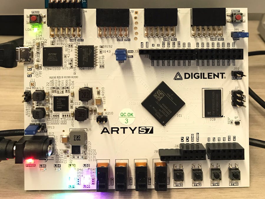
I've often wanted to be able to get status information from one of my FPGA systems while sitting in another room of my house. That way, as I am running tests, I can proceed to watch Netflix in another room or do some cooking in the kitchen while keeping a watchful eye on the status of the tests.
There are obviously a couple different ways to create this type of connection (Bluetooth 4, BLE, WiFi, Magnetic Induction? Infrared?). However, Digilent just released the Pmod ESP32 which is their own extension board featuring the ESP32 from Espressif. I had some previous experience with the ESP32 and I love the fact that I can do BLE, Bluetooth 4.1, and Wifi as well as acting as a server or client for TCP or SSL connections. I decided to pick up one of these new Pmods from Digilent and incorporate it into my system, and selected Wifi through TCP as the protocol to use. I made this decision due to the fact that I found a VERY simple TCP server example in python.
This project represents my first attempt at using the Pmod ESP32 to create some sort of wireless system.
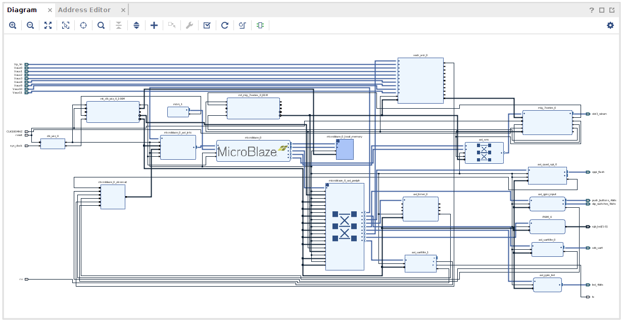
The Vivado ProjectI decided to use a Microblaze design for this FPGA as I wanted to write in C. The thought of implementing all of this in Verilog or VHDL made me shutter quite a bit. I'm not the biggest fan of Microblaze, but it is quite easy to use to get projects up and running. In addition to the microblaze portion of the hardware design, I added in two AXIuartlite controllers, one for interfacing with the Pmod ESP32 over Pmod connector JA, and one for using as a debug console over USB. I also brought some AXI gpio controllers into the design for interfacing with the switches, buttons, and LEDs on the board. There is also a PWM controller from Digilent, provided by their IP library here, to interface with the RGB LEDs. There is also an adc wizard in the design, but is unused in this project.
I set the AXI uartlite controllers to operate at 115200 baud. I am using the Pmod ESP32 in AT-command mode over UART, which defaults to 115200. I also should mention that this project was created with Vivado 2017.4.
The Pmod ESP32As I mentioned earlier, I planned to use the ESP32 in AT mode rather than standalone mode. The Pmod ESP32 comes from Digilent pre-loaded with the AT command firmware, so I did not need to flash anything new to the board. However, if you should need to re-flash the AT firmware onto the device, details and source can be found here. Details around the format of AT command can be found on the reference page for the Pmod.
Simple Python TCP ServerI found a very simple example of setting up a TCP server in python, and chose to work off that example for this project. The Python server is included on the Github repo and is 'server.py'. It is important that the IP address referenced in the server matches the IP address that your machine has been given by the router. Also, make note of this IP address and remote port as we'll use those to create a TCP connection from the ESP32.
Integrated ComponentsMy example program does not explicitly connect to the wifi network through software, though I have included some functions that should help anyone to be able to do this. Instead, I had already connected the device to my wifi network using a serial terminal. So, if you want to recreate this project, I recommend connecting the ESP32 to your network before trying to run this example or by adding a couple lines in main.c that tell the ESP32 to join the network before trying to initiate a TCP connection. It is also important that the example code in main.c is modified to your specific IP address of your server and remote Port number. I was using port 5005, but this can be realistically changed to almost anything.
Additionally, if you have some issues getting the project to work, use the button on the Pmod ESP32 to reboot the device. I had some issues getting the components to work nicely together on the first pass, but cycling power on the Pmod ESP32 caused things to work flawlessly. Also, it is important that the python server is already running when you start the program on microblaze.
Some Quick Steps:For the server... type 'python server.py' in whatever console or terminal you are using for your server. I was using a Macbook Air to act as the server, while the FPGA was running off of my Linux desktop.
For the FPGA:
The whole project is included in the repo, so you can skip bitstream generation in Vivado if you wish and move on to Vivado SDK, opening it with the workspace set to proj/base-rt.sdk in the repository. From here, you should be able to program the FPGA with the bitstream and run the microblaze application.
This is a very simple example and the messages passed wirelessly contain information about the states of the switches, LEDs, and buttons on the FPGA. However, one can see that it would be quite easy to convert this type of example into something more complex and useful.
Anytime the server receives data from the TCP socket, it simply prints it to the console. So all of the data formatting happens on the FPGA and data is sent as ascii.


Comments
Please log in or sign up to comment.