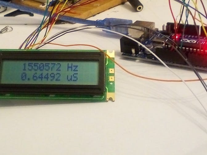
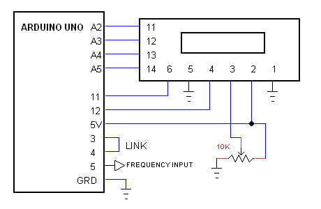
The Arduino generates an accurate 1 second time base for the counter by cascading timer0 and timer2. The link between digital inputs 3 and 4 connects the output of timer2, 250 Hz, to the input of timer0. The software waits for the output of timer0 to go positive to start the count of frequency input to timer1. Timer1 is a 16-bit timer: it overflows at the count of 2 power of 16, that in turn advances overFlow register. At the end of the 1st second, the 16 bit register is recorded. The Arduino then calculates the frequency and period and displays them on the LCD.
The frequency input is TTL signal levels; for low signal, a video amp has to be added. The specs recommend input up to 6 MHz; I tested it at 2 MHz.


_ztBMuBhMHo.jpg?auto=compress%2Cformat&w=48&h=48&fit=fill&bg=ffffff)


Comments
Please log in or sign up to comment.