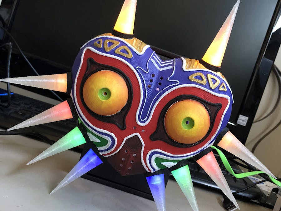
Simple story: I've always been a huge Legend of Zelda fan, saw this on Thingiverse, and had to make one. It's a 3D printed replica of Majora's Mask with 10 LEDs and an ESP8266 board. I have to give credit to lucidhack for both the 3D print AND the original idea. This is simply my implementation of it.
Video of dim lighting for glowing effects - you can tweak the code for different patterns
Step 1 - Print the Mask
You can use lucidhack's.stl files to slice according to your own printer. I used Cura for slicing and an ANYCUBIC I3 Mega for printing. You can print the mask as one piece and all of the horns/connectors in another. I used white PLA filament for the mask and clear PLA for the horns/connectors.
Step 2 - Paint It!
I'm horrible at painting so I got my lovely wife to help. Lucidhack has some techniques on how to get different finishes. We did straight-on acrylic paint - no other primers, coats, etc. and I think it turned out well.
1 / 3 • Wife did a good job :)
Step 3 - Wiring the Mask
I tested, soldered, and wired everything before putting the LEDs in the spikes and applying superglue. The pin-out for this can be found below along with the code. The wiring is straight forward with the exception of the multiple GND connections. What's going on in the back (see bottom gallery for picture):
ESP8266 - One of my favorites. Didn't utilize the wi-fi capabilities but thinking about changing the light pattern based on an event (e.g. someone streaming Majora's Mask on Twitch)
Mini-breadboard - This kept things somewhat organized. The sticky pad on that back allowed a semi-secure place for the ESP8266 (without having to secure it with something that could damage it) and a central point for connecting the wires.
Varying cable lengths - would recommend cutting to your needed length.
The soldered wires - probably a much cleaner way to do this. Since the board has only 4 GND outlets and we'll need a total of 10, we can combine multiple GND wires to go to a single GND pin. To do this, I just soldered 8 of them to two different wires (4 each) that went to GND. The top two LEDs got their own GND pins. It ain't pretty but it works.
1 / 2
Step 4 - Uploading the Code
The code is shown below in the.ino file. Connect the micro USB cable to the ESP8266 board and a computer. Bring up Arduino IDE (if you don't have it installed, you can get it here). In order to flash the ESP8266, you'll need install the right libraries in the Arduino IDE. This takes less than a minute to do with this guide.
1 / 2 • Testing the mask before we superglue the lights
Step 5 - Assembling the Mask
The rest of this is pretty straight forward
Super glue the lights into the small holes at the base of the horns.
Insert the small clear connectors into the horn sockets. The picture above has an example.
Set the horns onto the connectors and push down until snug against the outer rim of the sockets. Pay attention to the horns - they are different lengths. Again, lucidhack did a solid job documenting what's to be done.


Comments
Please log in or sign up to comment.