The ESP8266 is a great inexpensive device that gives you WIFI connectivity as well as a couple GPIO ports to connect sensors. In this project I will outline the following:
- Connect the ESP8266 to a USB to TTL Serial adapter to enable you to program the ESP8266 using the Arduino IDE.
- Upload code to take a reading from a DHT11 Temp/Humidity sensor and upload that to Adafurit IO using MQTT.
Here are the parts and pieces needed for this project
Connect the USB to Serial adapter and the sensor to the ESP8266 as outlined in the picture. Keep in mind you can get the adapter and the 8266 already integrated but whats the fun in that?? :)
***Note update- I originally had a picture showing the ESP8266 connected to 5V, I have updated showing 3.3V instead.
The ESP8266 has 8 pins:
RX VCC
GPIO0 RESET
GPIO2 CH PD
GND TX
The USB to serial adapter has 6 pins:
DTR RX TX VCC CTS GND
ESP8266
Connect RX on ESP8266 to TX on serial adapter
Connect VCC on ESP8266 to +3.3V
Connect GPIO0 to GND (This allows the ESP8266 to be programmed)
Connect GPIO2 on ESP8266 to DHT11 DAT pin
Connect CH PD on ESP8266 to +3.3V
Connect GNDon ESP8266 to Ground
Connect TX on ESP8266 to RX on serial adapter
NOTE: GPIO0 is very important. If you don't connect the pin to ground you will not be able to flash the 8266. After flashing you will want to disconnect so the sketch automatically runs if the 8266 is reset.
.
DHT11
Connect GND on DHT11 to Ground
Connect VCC on DHT11 to +5V or 3.3V
Verify DAT is connected to ESP8266 GPIO2 pin
Note: Some DHT11's come with 4 pins. They will still work with this project but note the pins.
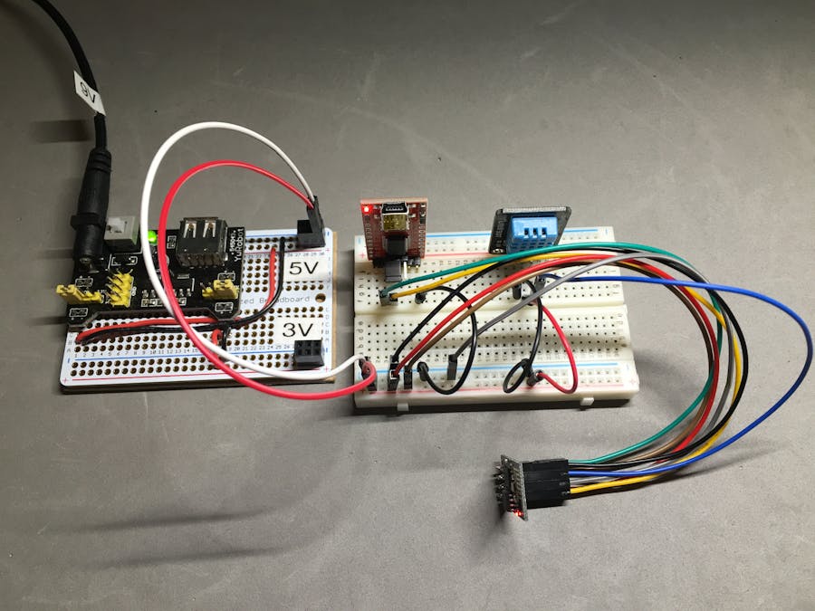
Once everything is connected it will look something like this disaster:
***Note Update- This picture show power connected to 5V. Connect power to 3.3V.
Uploading the code is pretty easy. The Arduino IDE now supports the ES8266! I am currently using version 1.6.7 on a Macbook Pro. Once you have the IDE downloaded and installed, connect a USB cable from your laptop/PC to the serial adapter and select the "Generic ESP8266 Module" from inside the IDE.
Then select the port. One note, the USB to serial adapter was automatically recognized by my Mac so I didn't have to search for a driver. Just keep in mind some generic modules may need a driver to be recognized.
Note: One thing before uploading the code, setup an account on Adafruit IO. You can upload the sketch and run it without creating an account, you just wont be able to see the data in a useful format.
You will need a few libraries as well (these are also linked in the code):
Adafruit_MQTT.h and the Adafruit_MQTT_Client.h
I won't go into details on MQTT since there is great info already out there. Here is a good link on Adafruit IO and MQTT. Here is a really good video as well. It explains what MQTT is and how to set it up and its use with Adafruit. It's free and a great addition to your projects After all, isn't it all about IoT!!!!! :)
Once these two steps have been done you should be able to upload the code. The code will attach to your wifi SSID and start communicating to Adafruit IO then it will start reading the sensor data and uploading a reading every 5 minutes.
For more information and troubleshooting, the sketch will print out messages in the serial monitor for more info on what its doing. Set the baud rate of the Serial monitor to 115200. You should see it attach to the wifi network and the start communication via MQTT to Adafruit IO.
Here is what the Adafruit Dashboard looks like once you sign in.
- Add IFTTT to this project
- Add GPIO pins to the ESP-01 board. Google add GPIO pins to ESP8266
I hope this is interesting and helpful and please provide me with any feedback as i am always willing to learn. Enjoy!!!


Comments