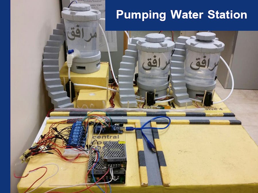
This is a helpful student project that teaches theory and application by applying all the courses learned especially the ones that are about Instrumentation, Process Application, Digital and Analog Electronics, and computer programming.
Delivery of the potable water requires little to no pumping, as the water is gravity fed from the large storage tank. But how it can be controlled and monitored?
SCADAThe project team selected Supervisory Control and Data Acquisition (SCADA) based pumping water station which is designed to collect field information, transfer it to central computer facility, and display real time operational data to the operator graphically or textually. SCADA can turn devices on or off remotely.
SCADA systems are designed to collect field information, transfer it to a central computer facility, and display the information to the operator graphically or textually, thereby allowing the operator to monitor or control an entire system from a central location in real time.
SCADA can:
- turn devices on or off
- display real time operational data
- provide equipment-wide to system-wide views of operation
- trend data, and alarms
- SCADA systems consist of both hardware and software.
The project team used the latest technology and components for the main instrumentation and control courses studied to develop this project.
The Process ModelTo achieve our aim which is a SCADA system, we had to build a process model (prototype) according to a drawing made by "VISIO" software:
Using three tanks, three pumps, and four valves, the actual model is as follows:
Install one ultrasonic sensor under each cover of the three tanks, thus, the water level in each tank can be measured.
All device wiring in the field gathered to one area. We called it "Central Control Room."
Until now, we have just been preparing our station. In the next part we will see how the control system was implemented.
Hardware Components of a SCADA System1. RTU (Remote Terminal Unit)
We used an Arduino board. All field equipment is connected to it. It is a representative of a standalone data acquisition and control unit, which monitors and controls equipment in the field. Besides that, the Arduino is connected to a tablet for local control in the field.
2. Communication (transmission system)
Communication hardware allows the transfer of information and data back and forth between the MTU (Master Terminal Unit) and the RTU. The APC220 radio module provides a simple and economic solution to wireless data communications. It integrates an embedded high speed microprocessor and high performance IC that creates a transparent interface. We connect it to the local tablet to transfer information to the MTU.
Here is how to configure it with Windows.
3. MTU (Master Terminal Unit)
We used a Touch-Screen computer placed in a central location with an operator as our MTU. It collects and logs information gathered by the field sites, displays information to the HMI (Human Machine Interface), and may generate action based upon detected events. The operator is able to make set point changes on the distant process.
The general communication flow is as follows:
We integrated between C# on the desktop and C++ on the Arduino via USB.
Our strategy here is to build a C++ program to run on the Arduino for the purpose of taking the three Ultrasonic sensor inputs and send them via USB. At the same time, it must listen to the port for any incoming command, such as, turn on the pump.
The desktop program made in C# to work as HMI gives the user control over the plant. We used Microsoft Blend to design the graphical interface and Microsoft Visual Studio for writing the actual code.
There are two directions the plant can work in:
1. Forward, where water travels from the Main tank to the City tank,
2. Backwards, where water comes back from the City tank to the Main tank.
As a result, we have to write the C# code to control these two paths.


_wzec989qrF.jpg?auto=compress%2Cformat&w=48&h=48&fit=fill&bg=ffffff)


Comments
Please log in or sign up to comment.