


Hardware components | ||||||
| × | 1 | ||||
| × | 1 | ||||
| × | 1 | ||||
 |
| × | 1 | |||
 |
| × | 1 | |||
Software apps and online services | ||||||
 |
| |||||
Control a small quadcopter via the OpenCV color tracking workflow incorporating the MSP430F2272 microprocessor. Created as a final project for ME461: Computer Control of Mechanical Systems taught at the University of Illinois at Urbana-Champaign.
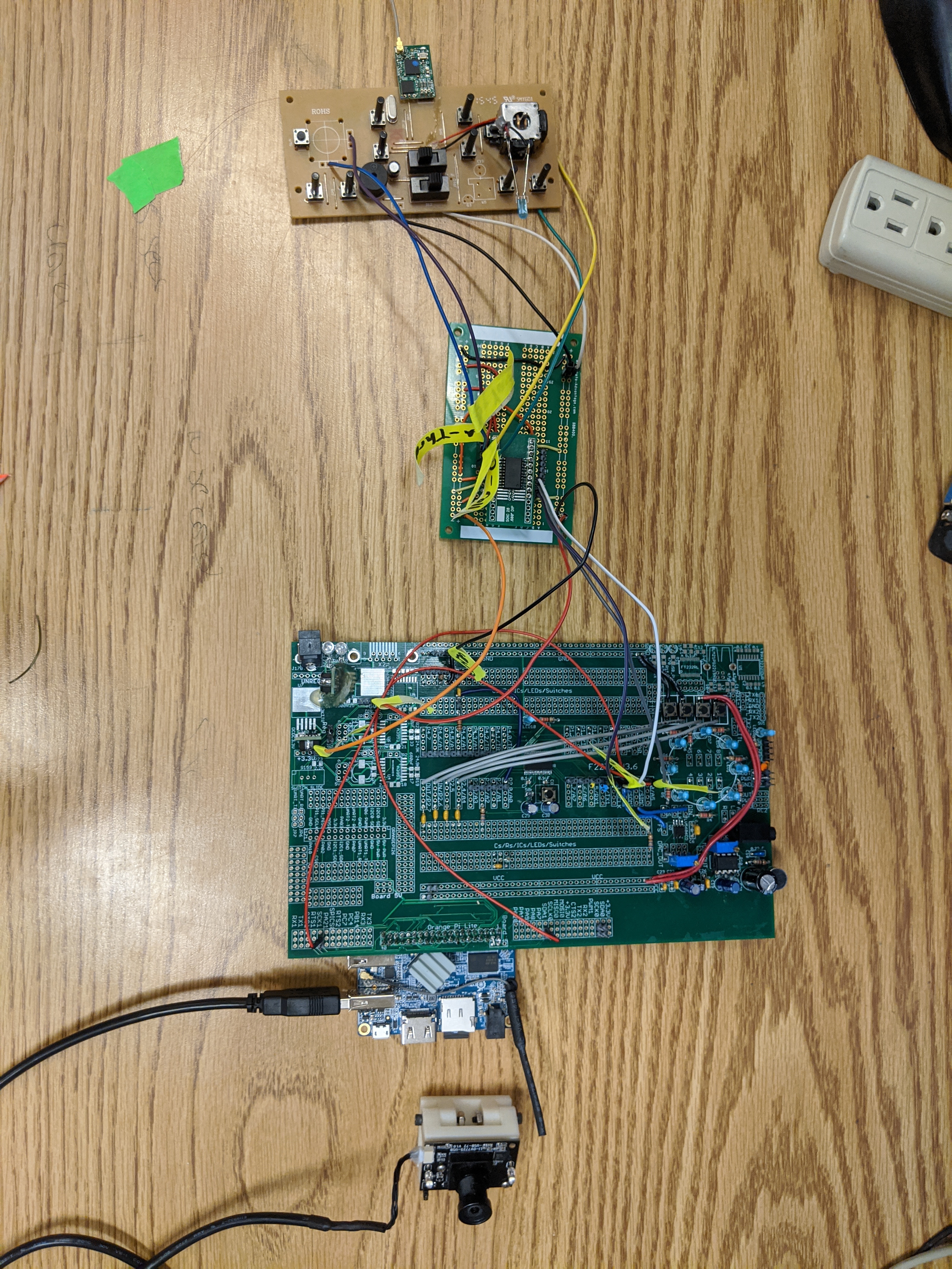
ProcessInitially, we wanted to control the quadcopter directly via digital communication between the MSP430 and the MLP4DSM Transmitter that came with the Blade Inductrix Quadcopter. Unfortunately, the data being sent from the Transmitter was encrypted before being sent to the wireless radio. This meant that we had to inject our control information as an analog signal in place of the thumb-sticks. We had previously worked with the MSP430 and a single channel DAC. But one channel was not going to be adequate; we needed four channels of digital input from the OrangePi running OpenCV as well as four channels of analog output to control throttle, yaw, pitch, and roll.
Earlier in the semester we had worked with single object color tracking with our OrangePi and the OpenCV library to set the angle of a servo motor via PWM output from the MSP430. Using the same base code on both the MSP430 and OrangePi, wemodified the code to track two objects of different colors as well as to calculate a delayed average center of the object. Every code loop, we calculate the center of each object by averaging the position of the pixels in it's color. We then record the center of both objects into four arrays (x1, x2, y1, y2). These centers are fed into a larger array of past measurements, and the average position over the last x samples is calculated. In order to increase the range we average over without overflowing our variables, this average is fed into another array, and the average of the last x averaged is calculated. This allows us to ~1 second delay between the current object center and it's average center.
With this delay we were able to smooth out any sudden movements in our hands. It also creates a control situation where holding your hands still means no inputs are given, which is helpful to regain control of the copter if it begins acting erratically. This control method worked smoothly for the directional inputs (yaw, roll, pitch), but made throttle difficult to fly with. Because of this, we decided to switch to an absolute control (distance from bottom of screen = control input) for the throttle.
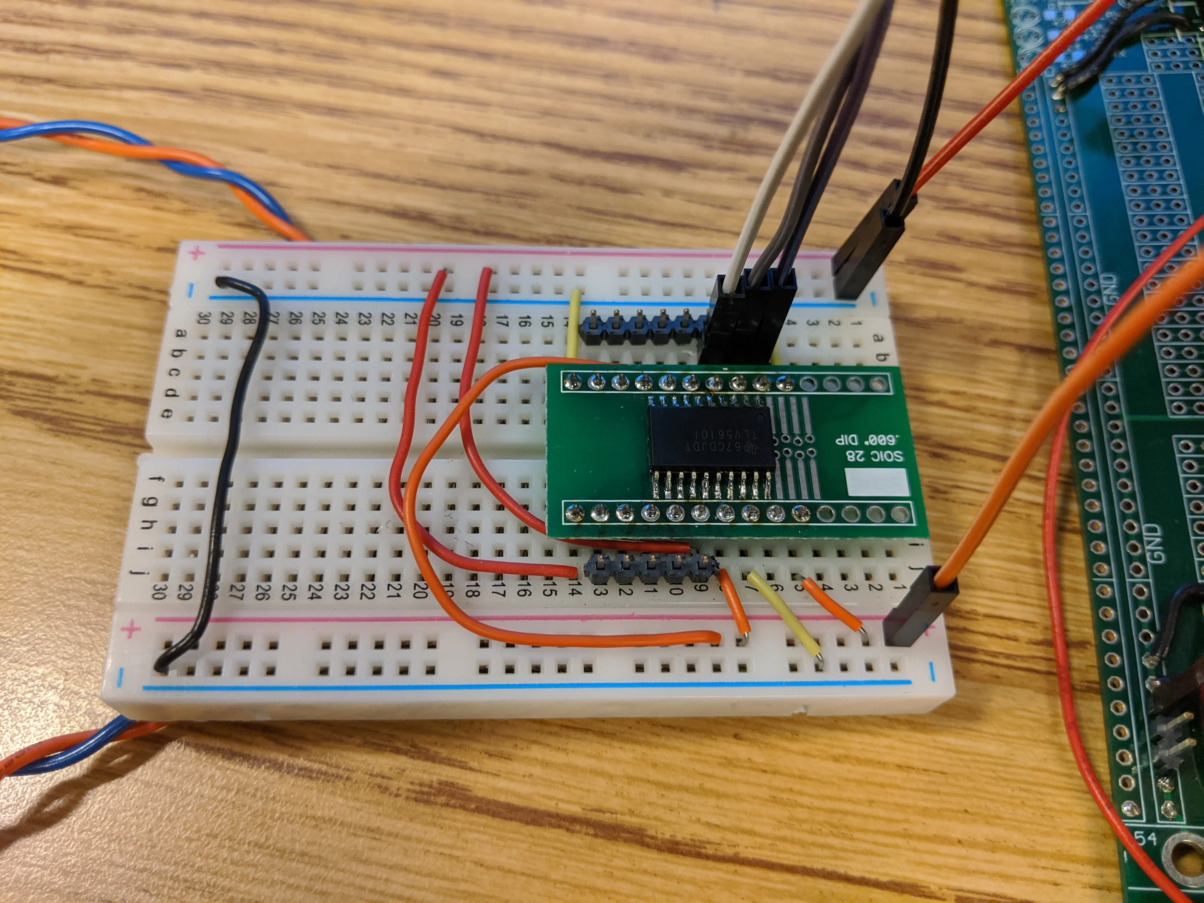
On the implementation side, we ran into a few issues with the wiring of the transmitter as well as communication with our TLV5610 DAC. These are discussed below in our issues section.
IssuesLighting conditions causing color shift on gloves
- Color tracking was based on HSV values for each pixel. Depending on where in the room the camera was located, the background lighting changed. Given that we didn't have a set location in the room where we would normally be working, we were required to modify the HSV values to match at each new location. We alleviated this by standing in the corner of the room, as is seen in the video below, where we had a clean background and consistent lighting. This corner also afforded us the ability to watch the drone while flying rather than having our backs to it.
SPI communication to TLV5610 DAC from MSP430
- This piece of the project was one of the more complicated ones simply because we weren't familiar with SPI communication. Once we passed the initial setup of the ports on the MSP430 using code developed earlier in the semester, we found that per the SPI protocol, timing of the communication commands was critical. Since we needed to send four input values to the DAC, we needed to make sure that the Frame Sync signal was being triggered in between each input being sent. This was done by separating the transmission of the data into two pieces as is seen here:
//DAC Transmission Function
void DAC_write(int DAC_data){
    LSB_data = DAC_data; //Lower 8 bits of data
    MSB_data = DAC_data>>8; //Upper 8 bits of data

    //Trigger FS pin high to low
    P3OUT |= 0x08;
    P3OUT &= ~0x08;

    msb_flag = 1; //MSB Data just filled buffer
    //Fill SPI TX Buffer and trip interrupt flag
    UCA0TXBUF = MSB_data;
}

//Excerpt of SPI RX Interrupt
#pragma vector=USCIAB0RX_VECTOR
__interrupt void USCI0RX_ISR(void) {

    if((IFG2&UCA0RXIFG) && (IE2&UCA0RXIE)) {
        if (msb_flag == 1){
            UCA0TXBUF = LSB_data; //Transmit LSB data
            //Set flag to 0 to prevent loop of empty data
            msb_flag = 0;
            byte_count++;
        }
        else{
        //As each set of data has completed, begin sending next piece
            if (byte_count == 1){
                DAC_write(yaw_val);
            }
            else if (byte_count == 2){
                DAC_write(pitch_val);
            }
            else if (byte_count == 3){
                DAC_write(roll_val);
            }
            else if (byte_count == 4){ //All data sent, reset to 0
                byte_count = 0;
            }
        }
        IFG2 &= ~UCA0RXIFG;
    }
Binding and Initialization of Blade Inductrix Quadcopter
- The method of binding the stock controller to the quadcopter is as follows:
- Turn on quadcopter and wait 5 seconds until lights start blinking
- Throttle on transmitter to middle, press throttle stick in, turn on transmitter, release stick and bring throttle to zero
- Wait until lights stop flashing and then fly.
With our modifications to the transmitter we were unable to provide zero throttle or press the button in on the stick. By replacing the button and making a small change to our code we were able to bind the quadcopter and transmitter together.
While that did solve one of our problems, every so often the quadcopter would get stuck in its initialization mode. After troubleshooting for a while, we realized the quadcopter has IMUs for its internal flight controller that needed to be stationary and level so as to prevent starting flight with sensor drift. Setting the quadcopter on the workbench after turning it on resolved this issue.
Quadcopter frame failure
- With the lightweight plastic frame of the quadcopter, we ran into an issue of the motor mounts breaking on hard landings. Although we did try to 3D print a new frame to replace the broken ones, we found that it was easier and more effective to superglue the motor mounts back in to their respective places. This did cause a small amount of imbalance and thus drift, which can be seen in our flight videos, but we were able to control the copter despite this.
Final Solution and Flight Testing


Comments
Please log in or sign up to comment.